1-9
Å
8
6
7
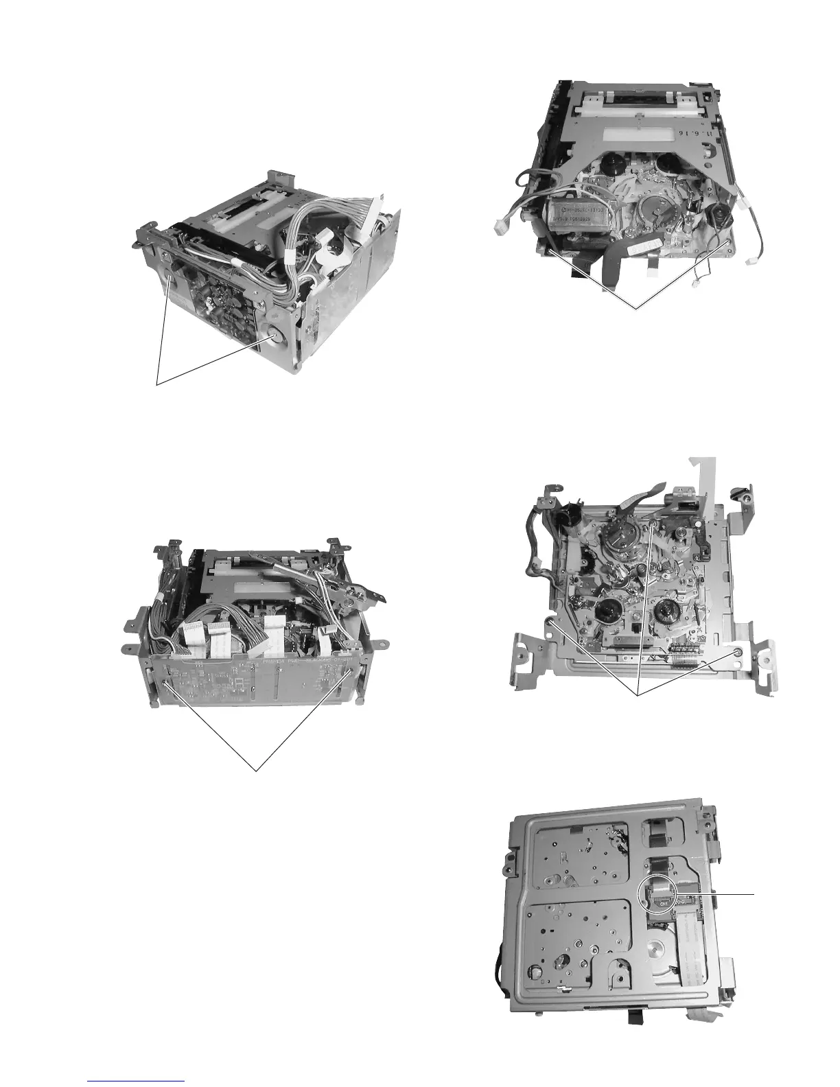
(4) Insulators (blue) are attached to the retaining screws. Be
sure to attach the insulators when re-assembling the side
stays.
(5) The side stays to both sides are attached in the same way.
Remove the 2 screws
6
and remove the side stays.
Fig. 1-7-4(2)
(2) When the remove the mechanism unit completely, also re-
move the connector
Å
from the rear.
Fig. 1-7-4(1)
1.7.4 Removing the Mechanism Unit
(1) Remove the 3 screws
8
. This allows the mechanism unit
to be removed from the stays When it is required to disas-
semble the mechanism unit itself, see SECTION 2.
Fig. 1-7-3
1.7.3 Removing the Cassette Housing Assembly
(1) Remove the 2 screws
6
and remove the cassette housing
assembly.
Fig. 1-7-2(5)
(6) After removing the rear stays and side stays (left and right),
remove the 2 screws
7
then remove the PR & MDA board.
When removing the PR & MDA boards, be careful not to
damage the wires and FFCs connecting them to the deck
assembly housing motor and power supply board.
Fig. 1-7-2(4)
6

 Loading...


