2-12
A BLOCK
B BLOCK
C BLOCK
D BLOCK
E BLOCK
F BLOCK
G BLOCK
H BLOCK
I BLOCK
°
Clutch lock
gear (1)
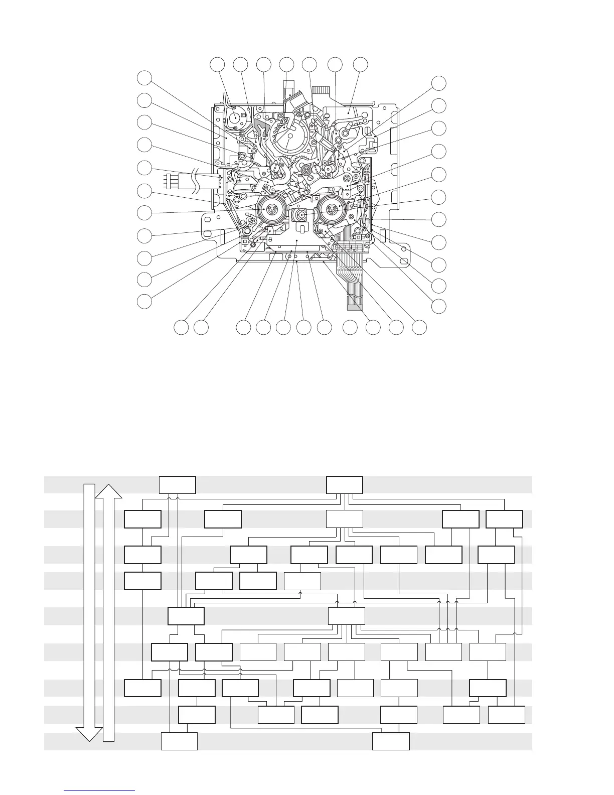
Disassembly Procedure
Assembly Procedure
1
Drum assembly
Å
Cassette
housing assembly
2
Motor bracket
assembly
3
Middle catcher
assembly
4
Reel cover
assembly
6
Sub-brake
assembly
5
Pinch roller
arm assembly
0
Swing arm
assembly
⁄
ENT guide base
assembly
7
Band arm
plate assembly
@
Main brake
(SUP) assembly
#
Main brake
(TU) assembly
%
Reel base
assembly (TU)
9
EXIT guide
arm assembly
^
Prism
¤
Worm wheel
2
8
Tension arm
sub-assembly
$
Reel base
assembly (SUP)
*
Guide rail
(TU) assembly
!
Sub-deck
assembly
‚
Brake control
arm assembly
(
Guide rail (SUP)
assembly
‹
Timing belt
£
Connect
gear 2 (TU)
·
Tension control
arm assembly
)
Base plate
assembly
&
Control plate
¡
Charge
arm assembly
›
Center gear
assembly
¢
Rotary encoder
assembly
fi
Reel drive
pulley assembly
∞
Main cam
™
Connect gear
2 (SUP)
fl
Push plate
•
Sub cam
q
Capstan motor
assembly
§
Arm gear 1
assembly
¶
Centering
arm assembly
‡
Clutch lock
gear (2)
º
Clutch lock
lever assembly
ª
Arm gear 2
assembly
w
Drum base
deck
2 19 42 1 18 41 3
17 12 36 20 4 32 26
10
33 24 1328
21
11
22
8
34
35
14
37
7
29
30
23
9
25
5
15
38
39
31
6
40
∼
2.6.4 Mechanism disassembly/assembly procedure chart
<How to read the chart>
⋅ The following chart shows the disassembly/assembly procedures by dividing them into blocks A to I.
⋅ To remove the tension arm sub-assembly which is located in block D; start disassembly from block A. The tension arm sub-assembly
can be removed as the fourth operation after the removals of the cassette housing assembly (block A) → reel cover assembly (block
B) → band arm plate assembly (block C).
⋅ The parts enclosed in thick frames are the maintenance parts listed in the maintenance table.
⋅ For details on the disassembly/assembly, see section 2.7, “Replacement of Major Parts”.
Fig. 2-6-1
Fig. 2-6-2
2-11

 Loading...


