125
rosrun clay_launch choose_map_for_localization.sh <path to map point cloud .ply file>
rosrun clay_launch choose_last_pose.sh <path to last_pose.txt file>
REMOTE COMMANDS NOT SUPPORTED
Stencil 2 does not support any of the tools or playback from a remote terminal at this point. This
includes sharpening, floor planner, loop closure or playback of raw data files.
COORDINATE TRANSFORMS FOR LOCALIZATION
This section provides information on the coordinate transforms and sensor messages generated
by Stencil 2 for use in localization. Stencil 2 passes messages using the open-source Robot
Operating System (ROS) communications protocol (for more information on ROS, visit
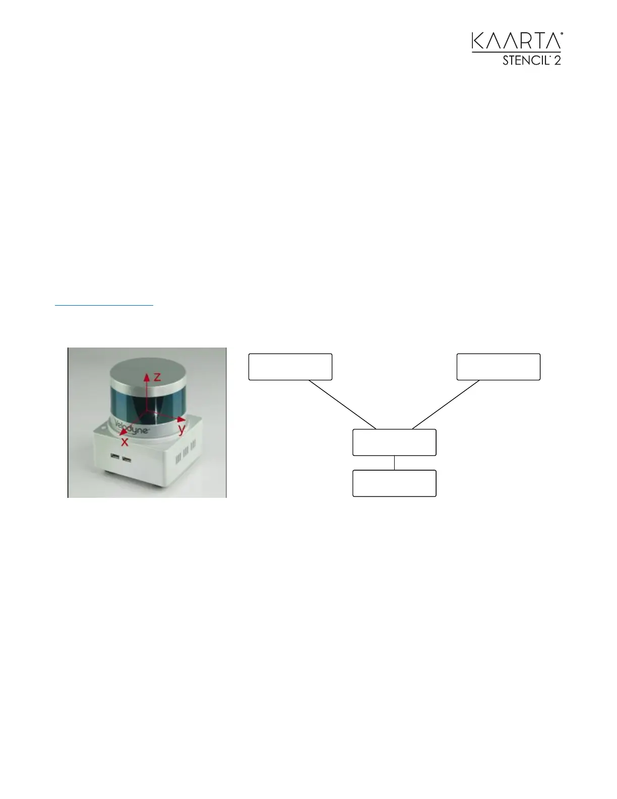
http://www.ros.org). The sensor frame origin is at the center of the Velodyne lidar as shown in
the following figure. The orientation is positive X-forward, Y-left, and Z-up. The Velodyne cable
points in the negative X-direction.
The block diagram shows the important transforms in the system. The right side of the diagram
from /sensor_init to /sensor is generated by odometry as nav_msgs::Odometry typed
messages on topic /integrated_to_init, representing relative pose of the sensor with
respect to the initial pose of the sensor.
The data flow on the left side of the diagram from /map to /sensor is produced by localization
(in the localization version only) as nav_msgs::Odometry typed messages on topic
/integrated_to_map, containing relative pose of the sensor with respect to the prior map.
Both of these messages are published at 200Hz. The two frames, /sensor and /Velodyne, are
the same frame linked by a static transform at 1Hz.
Definition of the frame is in the above figure when operating in mapping/localization without
camera. When using the Feature Tracker, the frame is centered at the front lens of the camera.
Offsets from the above figure are x = +0.0365, y = +0.825, and z = -0.0785.
/sensor
/map /sensor_init
/velodyne
/integrated_to_init
from odometry
/integrated_to_map
from localization
 Loading...