Installation Installation Manual
32 k2evo702 - 201610 Kaba c-lever and variants
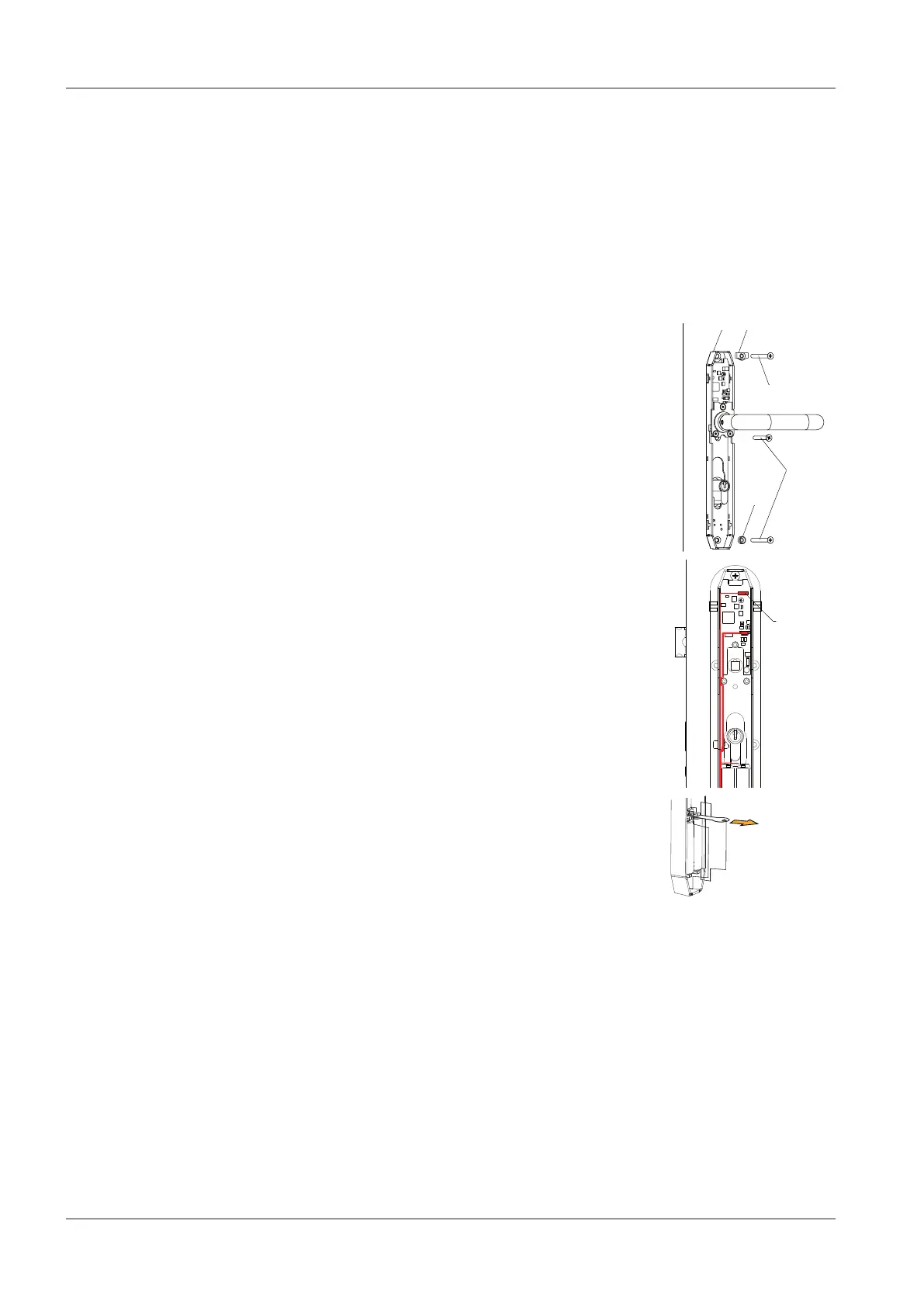
4.5.2 c-lever ES1 variant
Requirement:
• Outside shield installed
• Centring sleeve positioned in outside shield
• Mortise lock and lock cylinder installed
Procedure:
1.
Note: do not trap the antenna cable.
Place the internal fitting (26) with the inside lever
handle on the spindle and lock cylinder.
2. Screw in the top fixing screw (24) with a pull protec-
tion washer (35).
3. Screw in the middle fixing screw (24).
4. Screw in the bottom fixing screw (24) with a pull pro-
tection washer (36).
5.
Note: tightening torque max. 2.5±0.5Nm.
Secure the internal fitting and outside shield using
three fixing screws (24).
6. Insert the antenna cable plug into the socket (59) of
the e-module for the internal fitting.
7. Insert batteries if necessary.
8. If batteries are already inserted, remove the contact
protection film.
9.
Slip the battery protection film [}7.1] between the
batteries.
 Loading...