Operating Instructions Powador-proLOG_EN Page 1111
Se ction 5 · Installation
5.3.2 GSM antenna (XL GSM only)
5.3.3 Powador-go (M/L/XL only)
A patch cable is used to connect the power supply to the cur-
rent sensors. The ports are labeled “Powador go” (RJ45 sock-
ets).
5.3.4 Analogue/ISDN modem (L/XL)
Depending on the unit type, the Powador-proLOG units are
equipped with either an internal analogue or an internal ISDN
modem. The cable connection is included in the scope of deliv-
ery.
– Before you install the unit, use a telephone to test the
analogue/ISDN telephone connection in both directions
(incoming and outgoing connections).
– Use the included cable to connect the unit to the TAE
socket/NTBA.
– If you need to extend the cable, make sure that the
contacts are secure and the polarity is correct.
Powador-proLOG S Powador-proLOG L/XL
(analogue only)
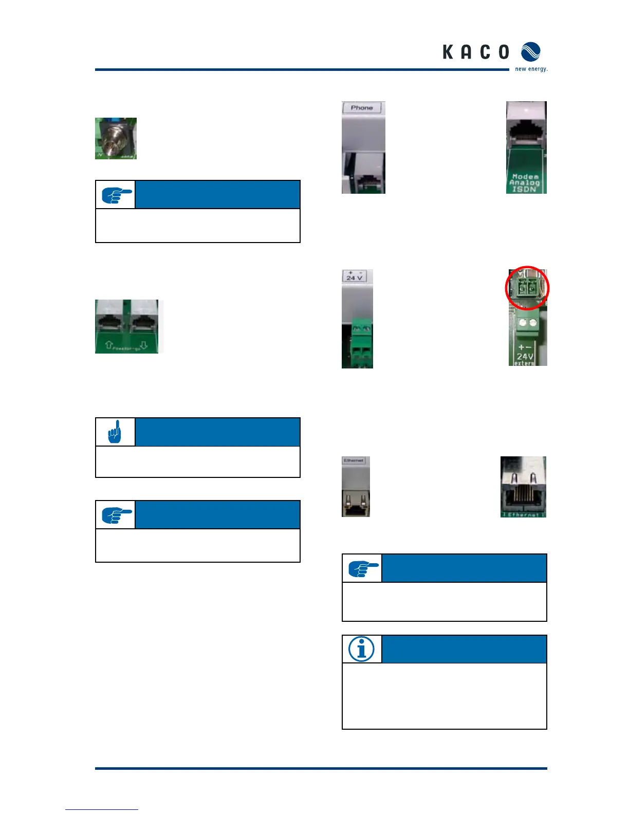
5.3.5 24-V supply
Powador-proLOG S Powador-proLOG M/L/XL
5.3.6 Ethernet
All Powador-proLOG models are equipped with a network
connection to connect the unit to an Ethernet network.
Powador-proLOG S Powador-proLOG M/L/XL
Connect the included GSM antenna here. The
connection is located to the far left, between
the grid connection and the Powador-go
RJ45 sockets.
Use this connection to provide
power from the unit’s internal
power supply to the external
sensors (max. 190 mA). The
socket is located between the
analogue/ISDN modem and
the Ethernet interface.
You can connect up to 100 current
sensors (Powador-go) to the “Powa-
dor-go” RJ45 sockets. For example,
you can use the current sensors to
include inverters without RS485 in
monitoring.
I M P O R TA N T
For more information on the Powador-proLOG with GSM
modem, see section 6.5 on page 22.
I M P O R TA N T
Use a cross-over cable to make a direct connection to
a PC or laptop computer. Use a standard patch cable to
connect to a hub or switch.
N OT E
At the factory, the Powador-proLOG is set to use an
IP address of 192.168.100.50 and a netmask of
255.255.255.0.
For detailed instructions on how to set up an Ethernet
connection, see section 7.2.
AT T E N T I O N
The internal power supply can be used to supply power to
a maximum of five current sensors.
I M P O R TA N T
When you have more than 32 bus devices, you need to
use a repeater.
 Loading...