Operating Instructions Powador-proLOG_EN Page 4343
Se ction 8 · Menu Description
Se ction 9 · Configuration Exam ple
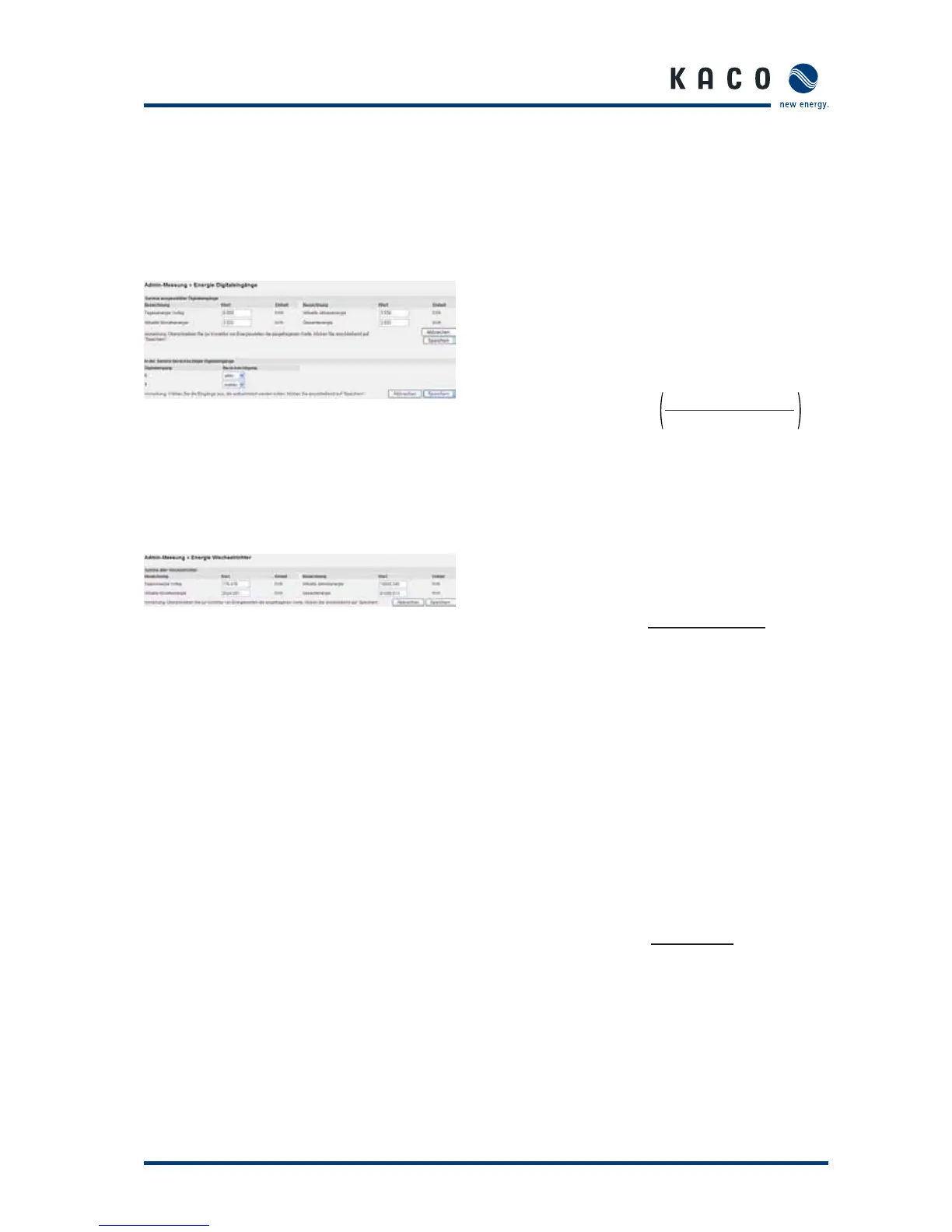
8.6.7 Digital Channel Energy
This page pertains to the “Online values >> Analogue/Dig-
ital” section: As the administrator, you can correct the energy
values that are displayed there.
You can also specify which channels should be included in the
total in the “Digital Inpus considered when summing up” sec-
tion.
8.6.8 Inverter Energy
If inverters are connected, you can use this section to correct
the energy values displayed in “Online values >> Sum of all
Inverters” .
The total will then automatically take all connected inverters
into account, so that there is nothing to select here.
8.6.9 Time Synchronization
Use this menu item to synchronise the system time on the
Powador-proLOG.
9 Configuration Example
9.1 Analogue inputs
9.1.1 Voltage input
Calculation rule for the relationship between the measured
value and the physical value:
Example 1:
A sensor with the sensor constant 10 V=1,500 W/m2 is to be
connected to an analog input. The full-scale value of the input
is 10 V.
This results in the gradient:
If the channel shows no offset during calibration, this is
entered as “0”.
If the channel shows an offset (e.g. +15 W/m2) during calibra-
tion, the following offset results:
Example 2:
A PT 1000 is to be connected to a cable via a measuring trans-
ducer. The measuring transducer supplies an output voltage of
0 V at -50 °C and an output voltage of 10 V at +100 °C.
This results in a physical full-scale value of 150 °C.
This results in the gradient:
The temperature is measured from -50 °C, resulting in the fol-
lowing offset:
[ Gradient ]
=
=
 Loading...