Page 1616 Operating Instructions Powador-proLOG_EN
OPTO <-> BEEPER
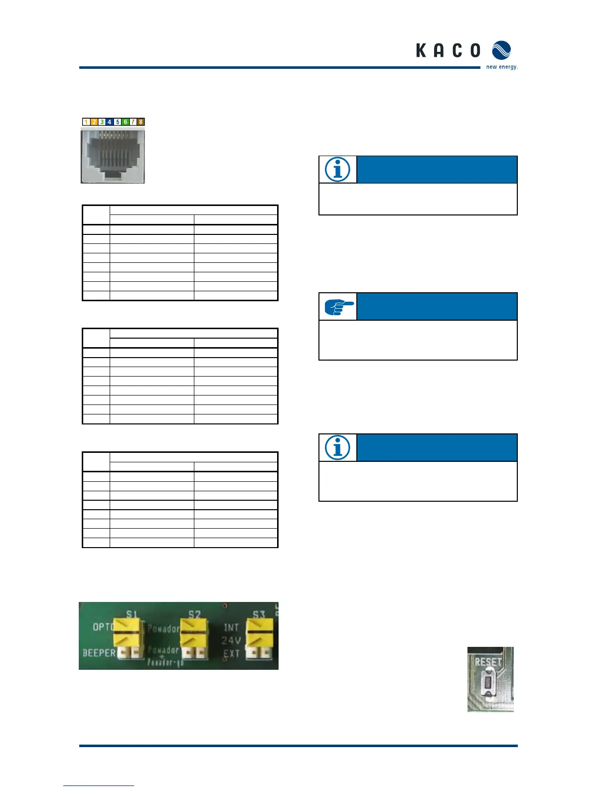
You can set the jumper to OPTO or BEEPER.
OPTO: Only the D0 output is activated.
BEEPER: The D0 output and the internal horn are activated.
Powador <-> Powador+Powador-go
You can set the jumper to Powador or Powador+Powador-go.
Powador:
The RS485 signal is only present at the “B A
RS485” terminal strip. Only the Powador invert-
ers can be operated.
Powador+Powador-go:
The RS485 signal is present at the “B A RS485” terminal strip
and at the “Powador-go” RJ45 sockets. The current sensors
and the inverters can be operated together.
24V internal <-> 24V external
You can set the jumper to INTERNAL or EXTERNAL. This
jumper affects the front socket of the “24V external” connec-
tion.
INTERNAL: The Powador-go units draw their power from
the internal power supply of the Powador-pro-
LOG.
EXTERNAL: An external voltage supply for the Powador-go
units can be connected to the “24V external”
terminal strip.
Reset
Use the reset button to
restart the Powador-proLOG.
5.5 Pin assignment
5.6 Jumper switch (M/L/XL only)
The Powador-proLOG M/L/XL has three jumper switches
located on the circuit board. You can set the following operat-
ing modes:
N OT E
The RS485 signal is internally bridged from the RJ45
“Powador-go” socket to the “B A RS485” terminal strip
using the “Powador+Powador-go” jumper setting.
RJ45 socket
Left: Pin 1
Right: Pin 8
Telefon PIN
Analog ISDN
1
2
3 STA / (B2)
4 b= minus SRA / (B1)
5 a= plus SRB / (A1)
6 STB / (A2)
7
8
EthernetPIN
Name Funktion
1 TPTX- Transmit Data
2 TPTX+ Transmit Data
3 TPTX+ Transmit Data
4
5
6 TPTX- Transmit Data
7
8
Powador-go PIN
Name Funktion
1 +12V…24V Versorgung
2 +12V…24V Versorgung
3 +12V…24V Alarmausgang
4 b= plus Datenleitung
5 a= minus Datenleitung
6 GND Alarmausgang
7 GND Versorgung
8 GND Versorgung
N OT E
The BEEPER should only be active when the D0 output is
used as an alarm output.
I M P O R TA N T
If only inverters are connected (without current sensors),
make sure the jumper is set to “Powador”. Otherwise,
you cannot communicate with the inverters.
Se ction 5 · Installation
 Loading...