Page 1212 Operating Instructions Powador-proLOG_EN
Se ction 5 · Installation
5.3.7 RS485 connection
Use a shielded twisted pair cable to connect the unit to the
RS485 bus (inverter <-> Powador-proLOG). The ports are
labelled “A” and “B”.
The maximum length of the RS485 bus is 250m. Bus connec-
tions as long as 1.2km have been tested in the field.
The last bus device must be terminated with a terminal resis-
tor. The Powador-proLOG is already terminated at the factory.
Each inverter is assigned a separate address (1 to 32).
Powador-proLOG S
A special cable with 6-pin connector is included for connect-
ing the inverters to an RS485 bus.
Plug the 6-pin connector into the Powador-proLOG S. Con-
nect the inverters to the open cable ends. You only need the
A and B wires.
Powador-proLOG M/L/XL
Connect the RS485 bus to the A/B screw terminals.
Powador-proLOG S Powador-proLOG M/L/XL
I M P O R TA N T
A maximum of 32 Powador and PVI inverters can be
operated at the same time. The number of Powador
25/30/33-kW central inverters is limited to a maximum of
10 units.
A Powador 25/30/33-kW central inverter occupies three
addresses in the Powador-proLOG. When you operate
Powador, PVI and 25/30/33-kW inverters at the same
time, do not exceed the maximum number of
32 addresses.
The Powador-proLOG S is limited to a maximum output
of 50kWp.
N OT E
Consult the relevant inverter manual for more information
on connecting and addressing the individual inverters.
I M P O R TA N T
After you have connected the inverters and current sen-
sors, make sure that the jumper switch is set to
“Powador+Powador-go”. If only inverters are connected,
set the jumper switch to “Powador”.
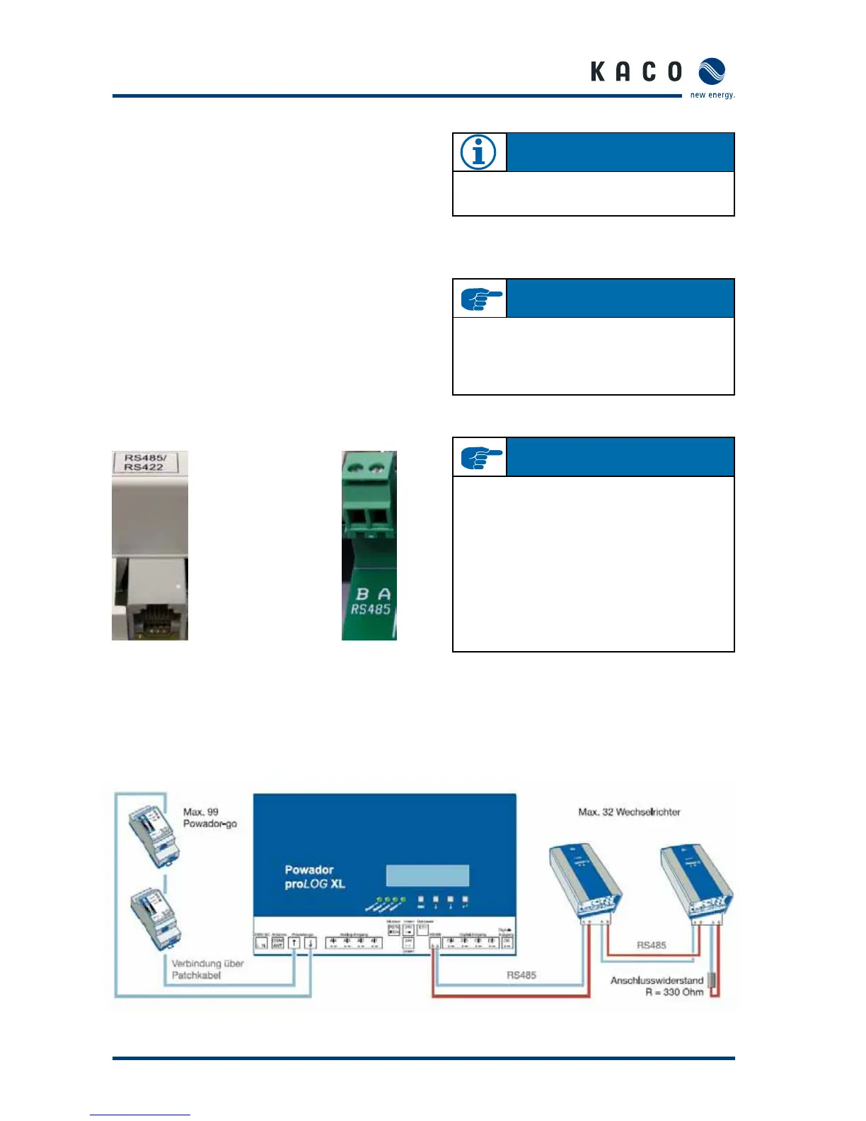
Schematic diagram for wiring inverters and current sensors
 Loading...