Operating Instructions Powador-proLOG_EN Page 1313
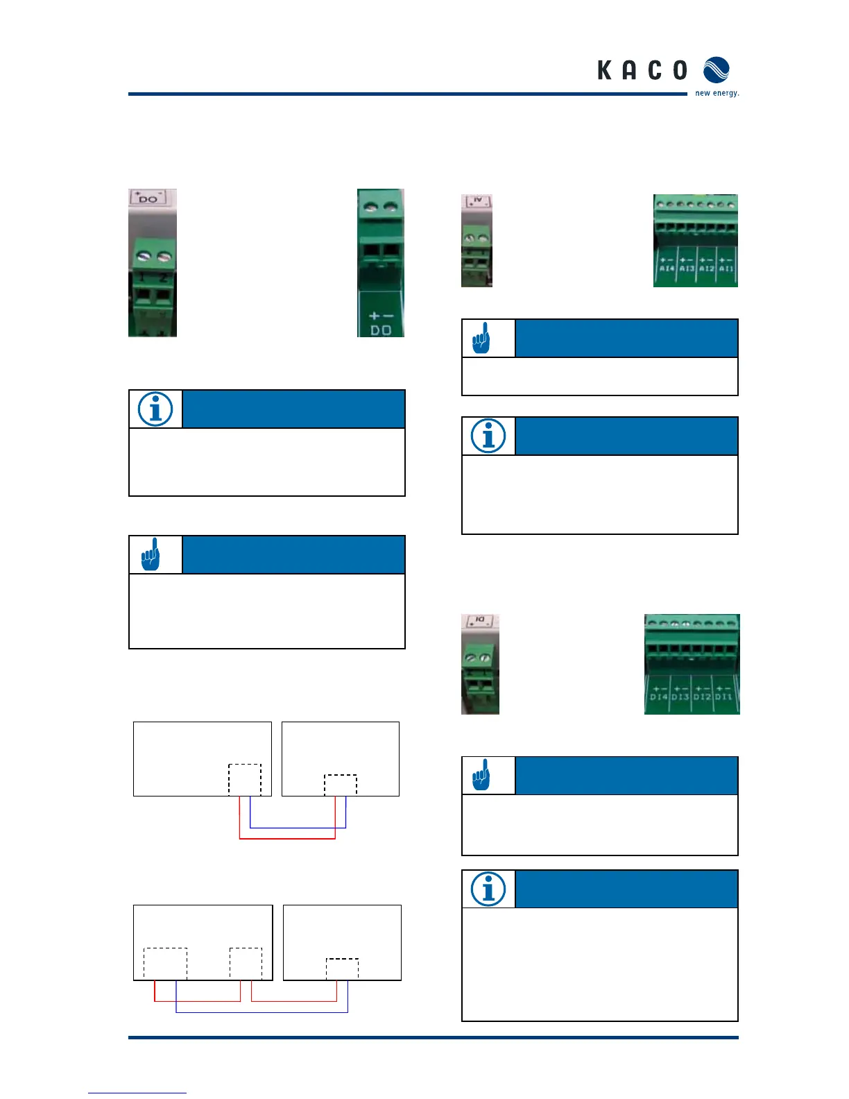
5.3.9 Analogue/digital inputs
The unit is equipped with four (XL) or one (S, M, L) analogue
input(s), which are configured for a voltage measurement of
from 0 to 10V.
Powador-proLOG S Powador-proLOG XL
Counter pulses (maximum frequency: 14Hz) can be recorded
using four (XL) or one (S, M, L) digital counter input(s). An
interface in accordance with the S0 specification must be
available.
Powador-proLOG S Powador-proLOG XL
5.3.8 Digital output D0
The digital output can be used as an alarm output to control
signaling devices or as a pulse output to connect a display.
Powador-proLOG S Powador-proLOG M/L/XL
Connecting a display to D0
Connecting a signaling device to D0
Powador-proLOG
+ -
D0
+ -
24V
+ -
Signalgeber
Se ction 5 · Installation
N OT E
To configure this function, connect to the Powador-
proLOG and make the required settings via “Admin moni-
toring – > Switching output” in your browser.
AT T E N T I O N
The output is designed as an optocoupler output (N/O
contact) and must therefore be connected with an exter-
nal voltage supply, if necessary. The maximum load is
50mA.
Impulseingang
Anzeigedisplay
Powador-proLOG
D0
+ -
+ -
N OT E
The analogue inputs can be optionally converted for cur-
rent measurement or resistance measurement.You do this
in the configuration menu of the Powador-proLOG (Admin
measurement – > Analogue channels.
AT T E N T I O N
Incorrect polarity or using an external voltage supply
greater than 24V can destroy the measuring input. The
24-V supply is available starting at terminal DI+.
AT T E N T I O N
Incorrect polarity or using a voltage supply greater than
12V can destroy the measuring input.
N OT E
The digital inputs can be optionally converted for status
evaluation.
This means that the Powador-proLOG can evaluate switch-
ing states 0 or 1 (N/C or N/O contact).
This must be set up using the configuration files for the
Powador-proLOG.
Please contact the hotline at KACO new energy GmbH.
 Loading...