6.5.3.2 Option W2/W3
Connecting the internal heat recovery system
Connecting the internal heat recovery system
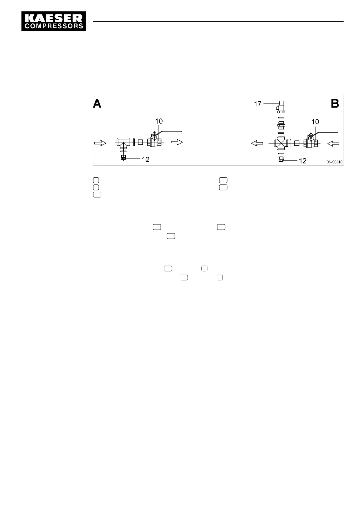
Fig. 14 Connecting the heat recovery system
A Outlet
B Inlet
10 Shut-off valve
12 Connection port with plug
17 Pressure relief valve
1. The user is to provide the following fittings:
■ Dirt trap with max. 0.1 mm strainer mesh
■ Shut-off valves 10 and connection ports 12 for maintenance and venting
■ Pressure relief valve 17 to prevent build-up of excessive pressure.
Blow-off pressure and capacity are governed by the user's installation design. The technical
specification of the heat exchanger must be taken into consideration.
2. Connect the supply lines and fittings.
3. Open the shut-off valve 10 at the inlet A .
4. Slowly open the shut-off valve 10 at the inlet B to gradually fill the heat exchanger with the heat
transfer medium.
5. Bleed the lines.
6 Installation
6.5 Options
9_5708 08 USE
Service Manual Screw Compressor
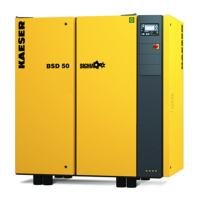
BSD
41
 Loading...