2. Slowly open the shut-off valve 7 to release pressure.
3. Withdraw the male hose fitting 6 and close the shut-off valve 7 .
10.15 Topping up the Cooling Oil
The machine must be isolated from the compressed air system and completely vented before
undertaking any work on the pressure system.
Material The hose coupling, shut-off valve and maintenance hose lie beneath the oil separator tank.
Precondition The power supply disconnecting device is switched off
The disconnecting device is locked in the off position
A check has been made no voltage is present
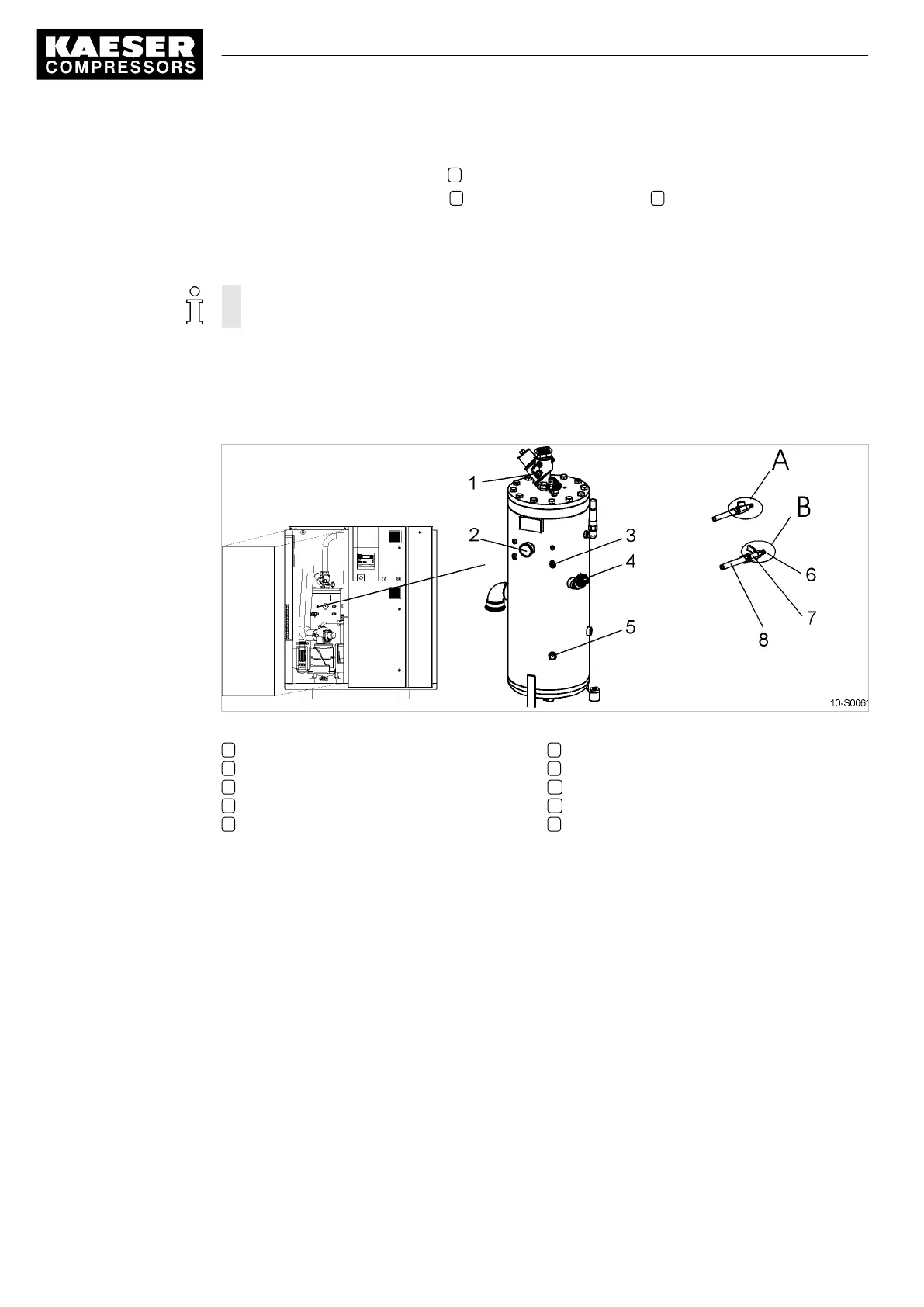
Fig. 31 Topping up the Cooling Oil
1 Hose coupling (air cooler venting)
2 Pressure gauge
3 Hose coupling (oil separator tank venting)
4 Oil filler with plug
5 Cooling oil level indicator
6 Male hose coupling/fitting
7 Shut-off valve.
A Shut-off valve open
B Shut-off valve closed
8 Maintenance hose
1. Vent the machine as described in 10.15.1.
2. Fill with cooling oil and test run as described in 10.15.2.
10.15.1 Venting the Machine (depressurizing)
The oil circuit vents automatically as soon as the machine is stopped.
Venting takes place in three stages:
■ Isolate the compressor from the compressed air system.
■ Vent air from the oil separator tank.
■ Vent air manually from the air cooler.
10 Maintenance
10.15 Topping up the Cooling Oil
76
Service Manual Screw Compressor
BSD 9_5708 08 USE