Seite 3.4 - 18 COMBIVERT R6-S © KEB, 2008-02
Digital in- and outputs
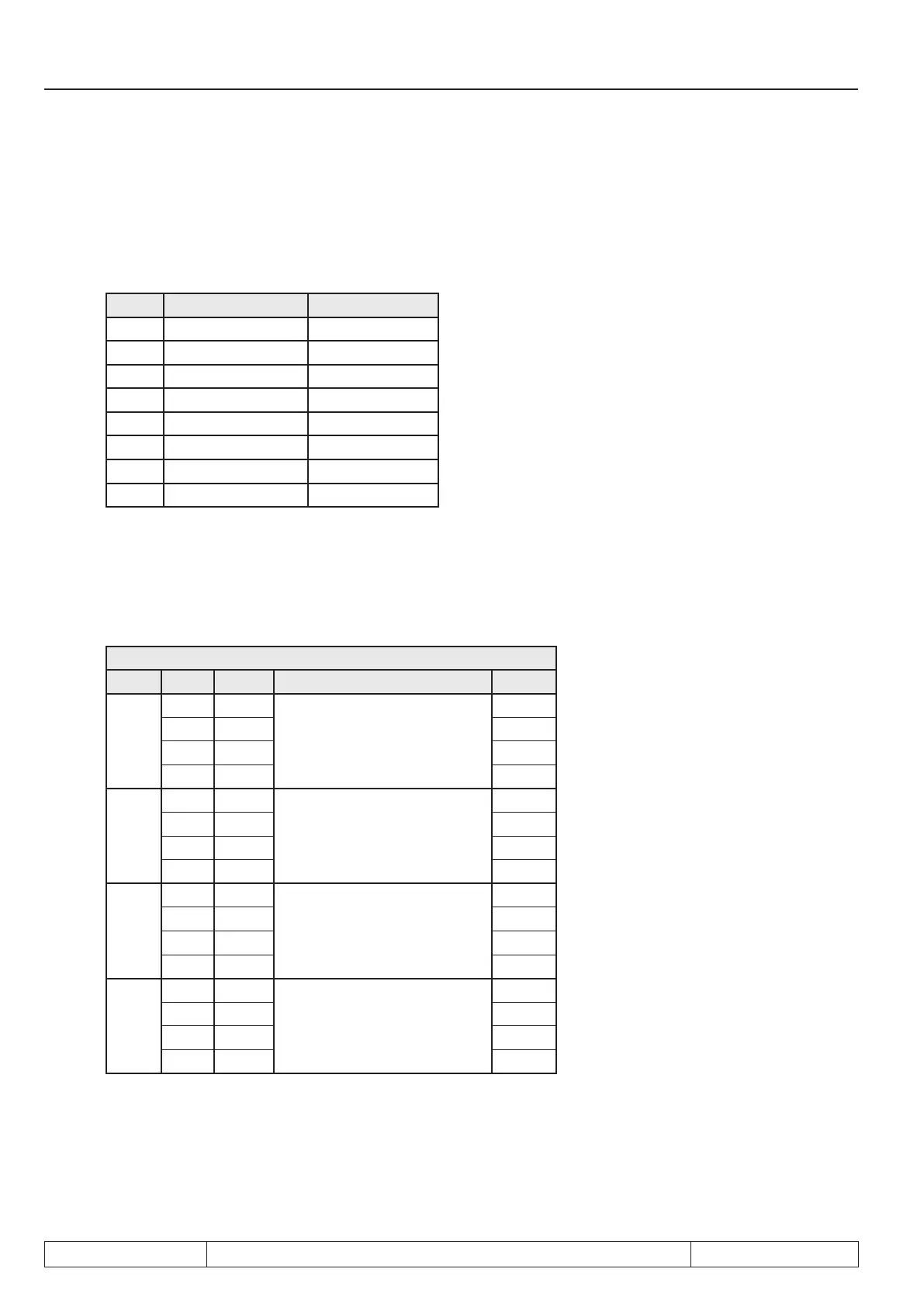
3.4.22 Output terminal state (ru.25) and digital output state (ru.80)
Parameter ru.25 displays the logical state of the digital outputs after the allocation by do.51. Parameter ru.80
displays the logical state before the allocation. If an output is set, the appropriate decimal value according to
the table below is output. If several inputs are set, the sum of the decimal values is output.
Name Function Decimal values
O1 Transistor output 1
O2 Transistor output 2
R1 Relay output 4
R2 Relay output 8
OA Internal output 16
OB Internal output 32
OC Internal output 64
OD Internal output 128
3.4.23 Hardware output allocation (do.51)
The output signals are assigned to output terminals O1, O2, R1 and R2 with parameter do.51. Allocation is
doneaccordingtothefollowingtable:
do.51: Hardware output allocation
Bit Value Signal Output Default
0 + 1
0 O1
O1 (terminal X2A.19)
x
1 O2
2 R1
3 R2
2+3
0 O1
O2 (terminal X2A.20)
4 O2 x
8 R1
12 R2
4+5
0 O1
R1 (terminal X2A.24...26)
16 O2
32 R1 x
48 R2
6+7
0 O1
R2 (terminal X2A.27...29)
64 O2
128 R1
192 R2 x
 Loading...

