"This is a message indicating that the instrument is not
calibrated properly, since calibration constants are stored in
NVRAM. The Model 197 remains at this point
if
the test fails,
but operation may be restored
for
troubleshooting by press-
ing either the
REL,
dB
or
DATA Logger buttons. The flashing
"C" annunciator indicates that the unit failed the NVRAM
test.
At this point try calibrating the instrument with the constants
already entered by simultaneously pressing
REL
and dB until
the CAL message is displayed. Then release the
REL
and dB
buttons. Simultaneously press the
REL
and dB buttons again
until the STOR message is displayed.
If
the error is corrected,
indicating that the NVRAM is probably good, a full calibra-
tion is required.
If
the error persists try replacing the NVRAM
chip,
U113.
Again the Model 197 must be completely
recalibrated after the problem is corrected.
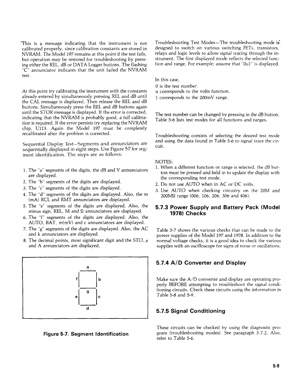
Sequential Display Test-Segments and annunciators are
sequentially displayed in eight steps. Use Figure
5-7
for
seg-
ment identification. The steps are
as
follows:
1.
The "a" segments of the digits, the dB and V annunciators
2. The "b" segments
of
the digits are displayed.
3.
The "c" segments of the digits are displayed.
4.
The "d" segments
of
the digits are displayed. Also, the m
(mA)
RCL
and
RMT
annunciators are displayed.
5. The "e" segments of the digits are displayed. Also, the
minus sign,
REL,
M and
Q
annunciators are displayed.
6.
The
"f"
segments of the digits are displayed. Also, the
AUTO, BAT, m(mV) and c annunciators are displayed.
7.
The
"g"
segments of the digits are displayed. Also, the AC
and k annunciators are displayed.
8.
The decimal points, most significant digit and the STO,
p
and A annunciators are displayed.
are displayed.
a
fl-I
9
C
el
I
d
Figure
5-7.
Segment Identification
Troubleshooting Test Modes-The troubleshooting mode
is'
designed to switch on various switching
FETs,
transistors,
relays and logic levels to allow signal tracing through the in-
strument. The first displayed mode reflects the selected func-
tion and range. For example; assume that
"Oul"
is displayed.
In this case,
0 is the test number.
u
corresponds to the volts function.
1
corresponds to the 200mV range.
The test number can be changed by pressing in the dB button.
Table
5-6
lists test modes for all functions and ranges.
Troubleshooting consists
of
selecting the desired test mode
and using the data found in Table
5-6
to signal trace the cir-
cuit.
NOTES:
1.
When a different function
or
range is selected, the dB but-
ton must be pressed and held in to update the display with
the corresponding test mode.
2. Do not use AUTO when in AC
or
DC volts.
3.
Use AUTO when checking circuitry on the 20M and
200MQ range
(006,
106,
206,
306
and
406).
5.7.3
Power Supply and Battery Pack (Model
1978)
Checks
Table 5-7 shows the various checks that can be made to the
power supplies
of
the Model 197 and 1978. In addition
to
the
normal voltage checks, it is a good idea to check the various
supplies with an oscilloscope for signs of noise
or
oscillations.
5.7.4
A/D Converter and Display
Make sure the A/D converter and display are operating
pro-
perly BEFORE attempting to troubleshoot the signal condi-
tioning circuits. Check these circuits using the information
in
Table 5-8 and 5-9.
5.7.5
Signal Conditioning
These circuits can be checked by using the diagnostic pro-
gram (troubleshooting modes). See paragraph 5.7.2.
Also,
refer to Table 5-6.
5-9
Artisan Technology Group - Quality Instrumentation ... Guaranteed | (888) 88-SOURCE | www.artisantg.com