SECTION
5
MAINTENANCE
5.1
INTRODUCTION
This section contains installation, service and calibration in-
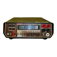
formation for the Model
197
and Model
1978.
Fuse replace-
ment, line voltage selection and troubleshooting procedures
are also included in this section.
WARN
I
NG
The procedures described
in this section
are intended for use by qualified service
personnel only. Do not perform these pro-
cedures unless qualified to do
so.
Many of
the steps covered in this section expose the
individual to potentially lethal voltages that
could result in personal injury or death if
normal safety precautions are not ob-
served.
5.2
TOP COVER REMOVAL/INSTALLATION
WARNING
Disconnect the line cord and remove all test
leads from the terminals of the Model 197.
1.
Remove the top cover as explained in paragraph
5.2.
2.
Remove the shield.
A.
Remove the screw that secures the shield to the mother
board. The screw is located at the rear of the shield.
B.
Carefully pull up on either side of the shield.
C.
Lift
the shield out of the Model
197.
3.
Position the battery board as shown in Figure
5-1
and
secure
it
to the shield using the two supplied screws. The
screws are positioned through the shield into the battery
board fasteners.
4.
Place the battery pack in the bracket and position on the
shield as shown. Route the two screws through the shield
into the bracket and tighten.
CAUTION
Do not allow the batterv leads to short
together or damage to the batteries may
occur.
The top cover of the Model
197
must be removed in order to
service the unit
or
install the Model
1978
battery pack and/or
the Model
1973
or
Model
1972 IEEE-488
interface. Proceed as
follows:
5.
Connect the red battery lead to the +RED terminal pin on
the battery board. Connect the black battery lead to the
-BLK terminal pin on the battery board.
WARN
I
NG
Disconnect the line cord and all other
equipment from the Model 197 before
removing the top cover.
CAUTION
Be careful not to reverse the wires (NOTE:
Red to Red and Black to Black).
1.
Turn off the powerr disconnect the line cord and remove all
6.
Carefully
place
the
shield (with battery pack) back
into
the
Model
197
so
that
it
seals properly on the
two
spacers.
~~~l~~~
retaining
Screw
in
the shield,
test leads from the terminals of the Model
197.
bottom of the case.
the rest of the unit.
to the bottom cover; replace top cover and screws.
2.
Turn the unit over and remove the four screws from the
3.
Turn the unit over again and separate the top cover from
4.
To reinstall the top cover, position the
tilt
bail properly in-
__I
NOTE
The retaining screw on the rear
of
the shield also
serves to connect the shield to circuit
LO.
5.3
BATTERY PACK (Model
1978)
INSTALLATION
7.
Connect the ribbon cable from the battery board to
P1009
on the mother board. Make sure pin
1
on the cable con-
nects to pin
1
of
P1009.
Refer to the detailed drawing of
Figure
5-1.
Refer to Figure
5-1
and perform the following procedure to in-
stall the battery pack:
5-1
Artisan Technology Group - Quality Instrumentation ... Guaranteed | (888) 88-SOURCE | www.artisantg.com

 Loading...