'
Model 197
AC
Voltage function is within specifications.
If
WARN
I
NG
Steps
1
through
4
require the use
of
high
voltage. Take care not to come into contact
with live circuits that could cause personal
injury or death.
desired refer to Section
3
Performance Verification.
Range
200mV
200rnV"
2
v
20
v
200
v
1.
Select the 750VAC range and set the calibrator to output
500.00V at 500Hz. Press the
REL
button
(REL
annunciator
turns on).
2. Set the calibrator to output 500.00V at 2OkHz. Verify that
the reading on the Model 197 is
000.00
k
150 counts. Press
REL (REL
annunciator turns off).
3. Set the calibrator to output 1OO.OOV at 500Hz and select
the 200VAC range. Press the REL button
(REL
annunciator
turns on).
4.
Set the calibrator to output 1OO.OOOV at 20kHz. Verify that
the reading on the Model 197 is 000.OOOV f200 counts.
Press
REL
(REL
annunciator turns off).
5. Set the calibrator to output 1O.OOOOV at 500Hz and select
the 20VAC range. Press REL
(REL
annunciator turns on).
6.
Set the calibrator to output 1O.OOOOV at 20kHz. Verify that
the reading on the Model 197
is
00.0000
f200 counts.
Press
REL
(REL
annunciator turns off).
Calibrator Calibrator Model
197
Voltage Frequency
Reading
190.000rnV
500Hz
190.000rnV
19.000niV
500Hz
19.000rnV
1.90000
v
500Hz
1.90000 V
19.0000
v
500Hz
19.0000 V
190.000
v
500Hz
190.000 V
If any of the above verifications are not met by the Model
197, the top cover must be removed and three trimmer
capacitors adjusted. The adjustments must be performed
within
10
minutes after the top cover is removed
so
that the
circuit components will be close to normal operating
temperature. The three trimmer capacitors (C103, C105 and
C107) are accessible through the shield. The shield and PC
board must be secured to the bottom cover in order to pre-
vent movement. This asssembly can be secured with two
screws and nuts (not supplied). Route the screws through the
bottom cover through the two brown spacers to the shield.
Secure the screws with the nuts. Also, use a flat blade, in-
sulated calibration tool for all the adjustments. Perform the
following steps in the exact sequence listed.
WARNING
Steps
1
through
4
require the use
of
high
voltage. Take care not to come into contact
with live circuits that could cause personal
injury or detah.
1.
Select the 750VAC range and set the calibrator to output
500.00V at 500Hz. Press the REL button
(REL
annunciator
turns on).
2. Set the calibrator to output 500.00V at 20kHz. Adiuz
C103 for
a
reading of
000.00
-t50
counts. Press
REL
(REL
annunciator turns
off.
3.
Set the calibrator to output 1OO.OOV at 500Hz and select
the 200VAC range. Press REL
(REL
annunciator turns on).
4.
Set the calibrator to output 1OO.OOV at 20kHz. Adjust
c105 for a reading on the Model 197
of
000.OOOV
+50
counts. Press REL (REL annunciator turns
off).
5. Set the calibrator to output 1O.OOOOV
at
500Hz and select
the 20VAC range. Press
REL
(REL
annunciator turns on).
6.
Set the calibrator to output
1O.OOOOV
at 20kHz. Adjust
C107 for a reading on the Model 197
of
00.0000V +50
counts.
7. Reinstall the top cover.
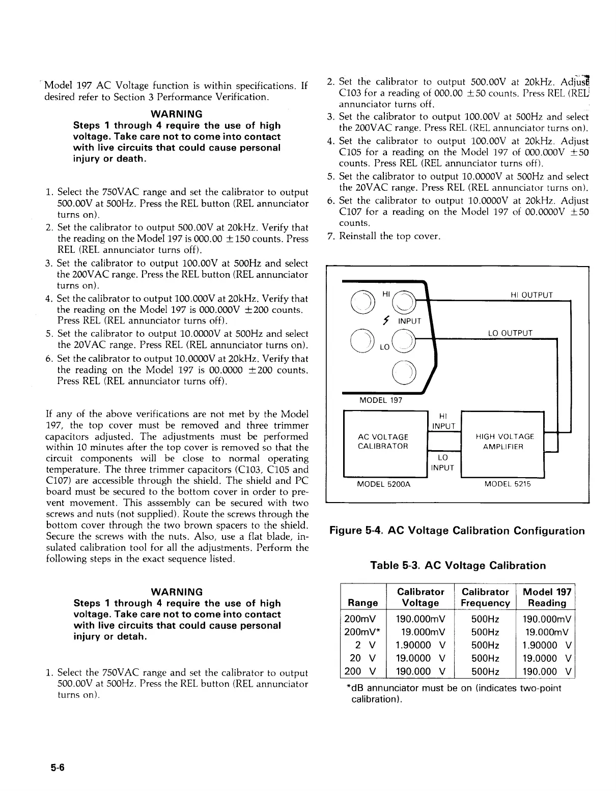
0
\
HI
OUTPUT
INPUT
LO OUTPUT
MODEL
197
MODEL
5200A
MODEL
5215
Figure
5-4.
AC
Voltage Calibration Configuration
Table
5-3.
AC Voltage Calibration
5-6
Artisan Technology Group - Quality Instrumentation ... Guaranteed | (888) 88-SOURCE | www.artisantg.com