WARNING
The following procedures require that high
voltages may be applied to the input ter-
minals of the Model 197. Use normal safety
precautions to avoid possible electrical
shock which could result in personal injury
or death.
3.5.1
DC
Voltage
Accuracy Check
1.
Select the
DC
volt function and autorange.
CAUTION
Do not exceed IOOOV between the input HI
and
LO
terminals or damage to the instru-
ment may occur.
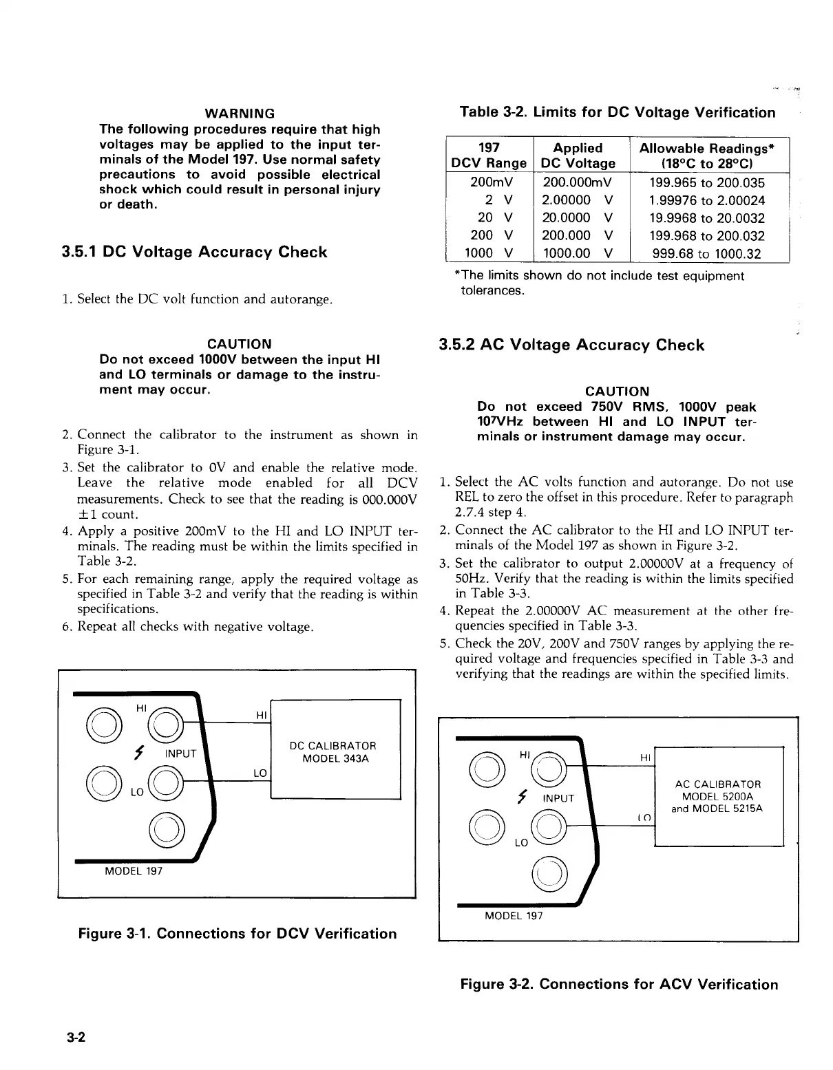
2. Connect the calibrator to the instrument as shown in
Figure
3-1.
3. Set the calibrator to
OV
and enable the relative mode.
Leave the relative mode enabled for all DCV
measurements. Check to see that the reading is 000.OOOV
+1
count.
4.
Apply a positive 200mV to the
HI
and
LO
INPUT
ter-
minals. The reading must be within the limits specified in
Table 3-2.
5. For each remaining range, apply the required voltage as
specified in Table 3-2 and verify that the reading is within
specifications.
6.
Repeat all checks with negative voltage.
I
MODEL 197
Figure 3-1. Connections for DCV Verification
-
.,?
Table 3-2. Limits for DC Voltage Verification
197
DCV Range
200mV
2v
20
v
200
v
1000
v
Applied
DC Voltage
200.000mV
2.00000
v
20.0000
v
200.000
v
1000.00
v
Allowable Readings*
(18OC to 28OC)
199.965
to
200.035
1.99976
to
2.00024
19.9968
to
20.0032
199.968
to
200.032
999.68
to
1000.32
I
*The limits shown do not include test equipment
tolerances.
3.5.2
AC
Voltage
Accuracy Check
CA UTlO N
Do not exceed 750V RMS, IOOOV peak
107VHz between HI and
LO
INPUT ter-
minals or instrument damage may occur.
1.
Select the AC volts function and autorange. Do not use
REL
to zero the offset in this procedure. Refer to paragraph
2.7.4 step
4.
2. Connect the AC calibrator to the HI and
LO
INPUT ter-
minals of the Model 197 as shown in Figure 3-2.
3.
Set the calibrator to output 2.OOOOOV at a frequency of
50Hz. Verify that the reading is within the limits specified
in Table
3-3.
4.
Repeat the 2.OOOOOV AC measurement at the other fre-
quencies specified in Table 3-3.
5. Check the 2OV, 2OOV and 750V ranges by applying the re-
quired voltage and frequencies specified in Table
3-3
and
verifying that the readings are within the specified limits.
HI
AC
CALIBRATOR
MODEL 5200A
and
MODEL 5215A
10
MODEL 197
Figure 3-2. Connections for ACV Verification
3-2
Artisan Technology Group - Quality Instrumentation ... Guaranteed | (888) 88-SOURCE | www.artisantg.com