dBm measurements, referenced to another impedance, can be
read directly from the display of the Model 197 by utilizing
the
REL
feature, and an accurate voltage source. The basic
procedure is as follows:
1.
Calculate
or
look up the equivalent voltage level (Table
2. Input that voltage level to the Model 197.
3. With the Model 197 in the
dB
mode, press the
REL
button.
4.
dBm measurements referenced to the desired impedance
can now be read directly from the display
of
the Model
197.
2-6) for OdBm at the desired reference impedance.
dBW
Measurements
dBW is defined as decibels above
or
below a one watt
reference. The procedure
is
the same as that found in
paragraph 2.7.9 step 2.
The only difference is that the
reference point is OdBW (1W) rather than OdBm (1mW).
dBV
Measurements
dBV is defined as decibels above or below 1V (OdBV point).
This is a voltage relationship independent of impedance. The
basic procedure is to simply subtract 2.22 dB (Table 2-6) from
all subsequent displayed readings on the Model 197.
Relative
dB
Measurements
Just about any voltage level within the measurement limit of
the Model 197 can be established as the OdB point. The basic
procedure is to establish the level as the OdB point by using
REL and make the desired dB measurements.
2.7.10
dB Measurement Considerations and
Applications
1.
Typical Instrument Performance
Typically, the Model 197 will perform better that its
published dB specification. The following example will
il-
lustrate this point:
A.
B.
C.
Using the Model 197 in the dB mode (6003 ref) measure
a ImV
RMS,
1kHz source (common application in the
communications field). Typically, the Model 197 will
read -57.7dBm.
The calculated dBm level for that source is -57.8dBm.
The O.1dBm error is considerably better than the
+
2dBm specification. The specifications are intended
to cover worst measurement conditions.
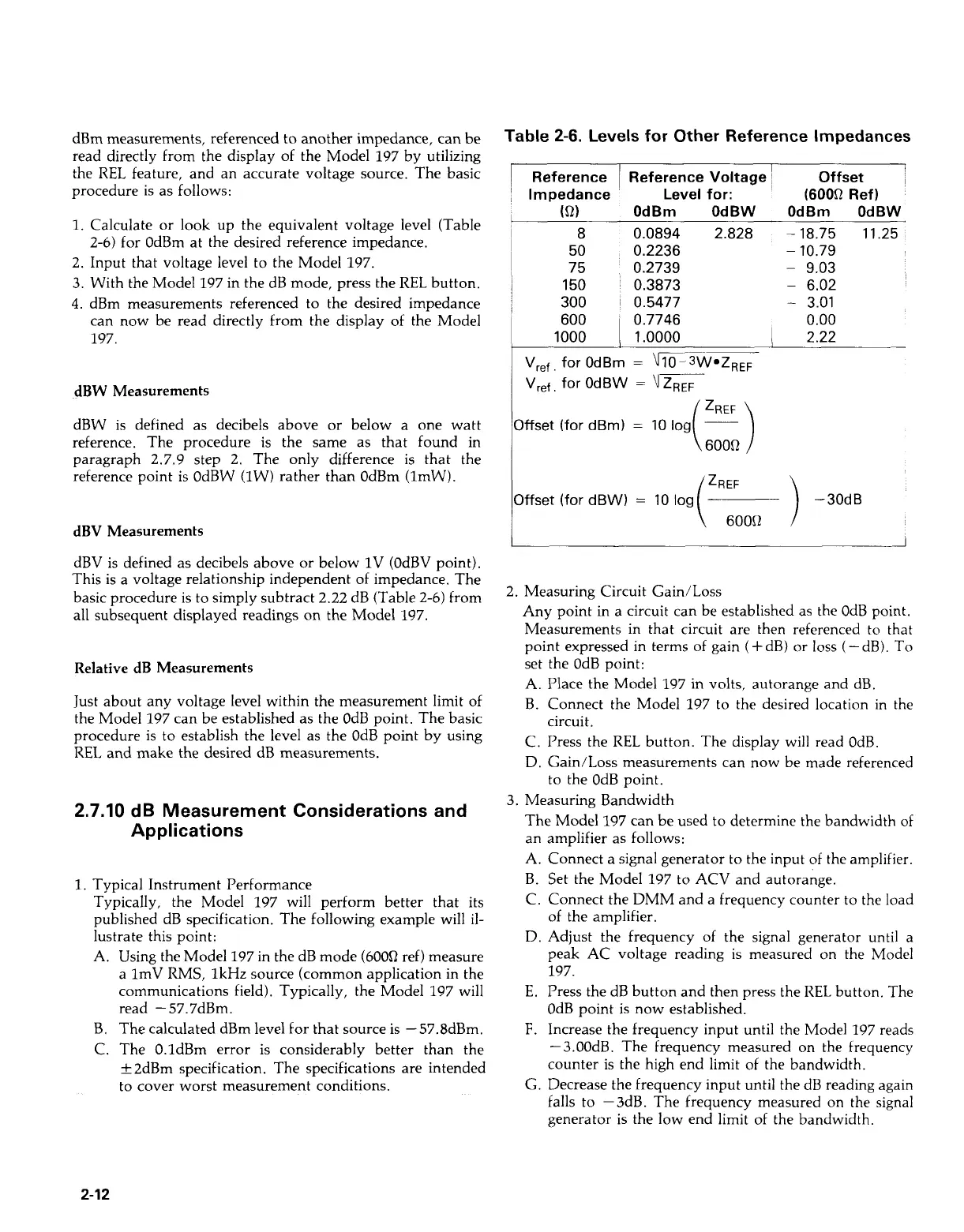
Table
2-6.
Levels for Other Reference Impedances
I
Reference
1
Reference Voltage
I
Offset
'
Impedance
I
I
I
(Q2)
8
50
75
150
300
~
~
Vref
for
OdBm
Level for:
OdBm OdBW
0.0894 2.828
0.2236
0.2739
0.3873
0.5477
0.7746
1
.oooo
'
(600Q
Ref)
OdBm OdBW
-
18.75 11.25
-
10.79
-
9.03
-
6.02
-
3.01
0.00
I
2.22
.
Vref,
for
OdBW
=
\
ZREF
Offset
(for
dBm)
=
10
log
~
Cblb:!)
Offset
(for
dBW)
=
10
log
(zR:ooQ
)
-30dB
2. Measuring Circuit Gain/Loss
Any point in a circuit can be established as the OdB point.
Measurements in that circuit are then referenced to that
point expressed in terms of gain (+dB) or
loss
(-dB). To
set the OdB point:
A. Place the Model 197 in volts, autorange and dB.
B.
Connect the Model 197 to the desired location
in
the
circuit.
C. Press the
REL
button. The display will read OdB.
D. Gain/Loss measurements can now be made referenced
to the OdB point.
3. Measuring Bandwidth
The Model 197 can be used to determine the bandwidth of
an
A.
B.
C.
D.
E.
F.
G.
amplifier as follows:
Connect a signal generator to the input of the amplifier.
Set the Model 197 to ACV and autorange.
Connect the DMM and a frequency counter to the load
of the amplifier.
Adjust the frequency of the signal generator until a
peak AC voltage reading is measured on the Model
197.
Press the dB button and then press the
REL
button. The
OdB point
is
now established.
Increase the frequency input until the Model 197 reads
-
3.00dB. The frequency measured on the frequency
counter is the high end limit of the bandwidth.
Decrease the frequency input until the dB reading again
falls to -3dB. The frequency measured on the signal
generator is the low end limit of the bandwidth.
2-12
Artisan Technology Group - Quality Instrumentation ... Guaranteed | (888) 88-SOURCE | www.artisantg.com