4.3V OHMS
SOURCE
i
Q105
-
Q106
a109
-
-
RX
INPUT
HI
0
SENSE
HI
i-
->
-
3
TO Q113
OF
Q
SENSE LO
i
::I-
..-
MULTIPLEXER
->TO
Q112 OF
MULTIPLEXER
K103
1
.'
A
12
REF
LO
'TO Q110
OF
MULTIPLEXER
4.3.6
AC Converter
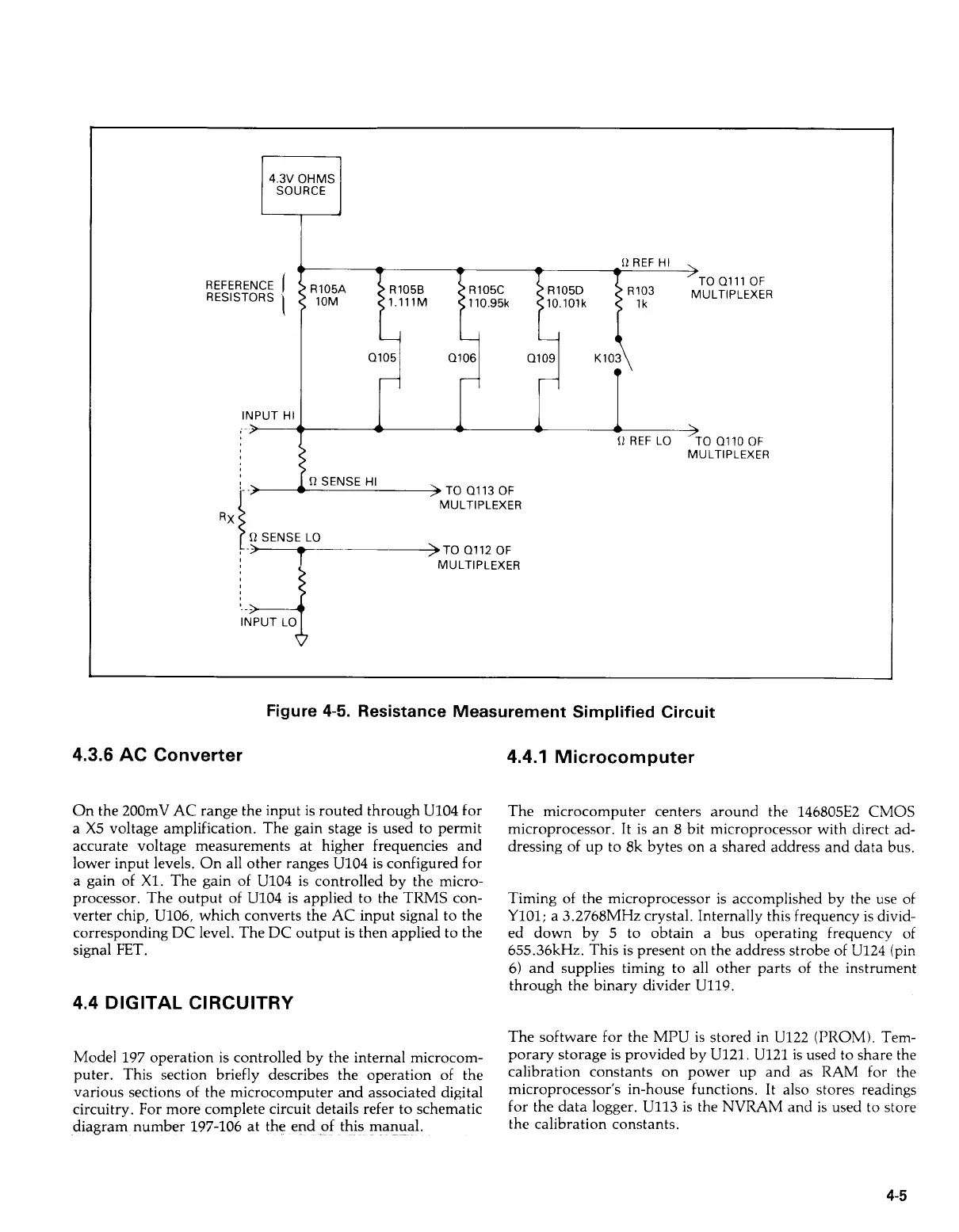
Figure
4-5.
Resistance Measurement Simplified Circuit
On the
200mV AC
range the input is routed through
U104
for
a
X5
voltage amplification. The gain stage
is
used to permit
accurate voltage measurements at higher frequencies and
lower input levels. On all other ranges
U104
is configured for
a gain of
X1.
The gain
of
U104
is controlled by the micro-
processor. The output of
U104
is applied to the TRMS con-
verter chip,
U106,
which converts the
AC
input signal to the
corresponding
DC
level. The
DC
output is then applied to the
signal
FET.
4.4
DIGITAL CIRCUITRY
Model
197
operation is controlled by the internal microcom-
puter. This section briefly describes the operation of the
various sections of the microcomputer and associated digital
circuitry. For more complete circuit details refer to schematic
diagram number
197-106
at the end of this manual.
4.4.1
Microcomputer
The microcomputer centers around the
146805E2 CMOS
microprocessor.
It
is an
8
bit microprocessor with direct ad-
dressing
of
up to
8k
bytes on a shared address and data bus.
Timing of the microprocessor is accomplished by the use of
Y101;
a
3.2768MHz
crystal. Internally this frequency is divid-
ed down by
5
to obtain a bus operating frequency
of
655.36kHz.
This is present on the address strobe of
U124
(pin
6)
and supplies timing to all other parts of the instrument
through the binary divider
U119.
The software for the
MPU
is stored in
U122 (PROM).
Tem-
porary storage is provided by
U121. U121
is used to share the
calibration constants on power up and as
RAM
for the
microprocessor's in-house functions.
It
also stores readings
for the data logger.
U113
is the
NVRAM
and is used
to
store
the calibration constants.
4-5
Artisan Technology Group - Quality Instrumentation ... Guaranteed | (888) 88-SOURCE | www.artisantg.com