Front Panel Operation
4-60
Meter:
Arm Layer:
Arm Source = Immediate
Arm Count = 1
Arm Trigger Control = Acceptor
Scan Layer:
Scan Source = Immediate
Scan Count = 1
Scan Trigger Control = Acceptor
Measure Layer:
Measure Source = TrigLink
Trigger Link Mode = Semi-Synchronous
Semi-Sync Line = #1
Trigger Control = Acceptor
Measure Count = 10
To run the test, simply press TRIG on the meter to take
it out of the idle state and then press STEP on the Mod-
el 7001. The following explanation on operation is ref-
erenced to the operation model shown in Figure 4-29.
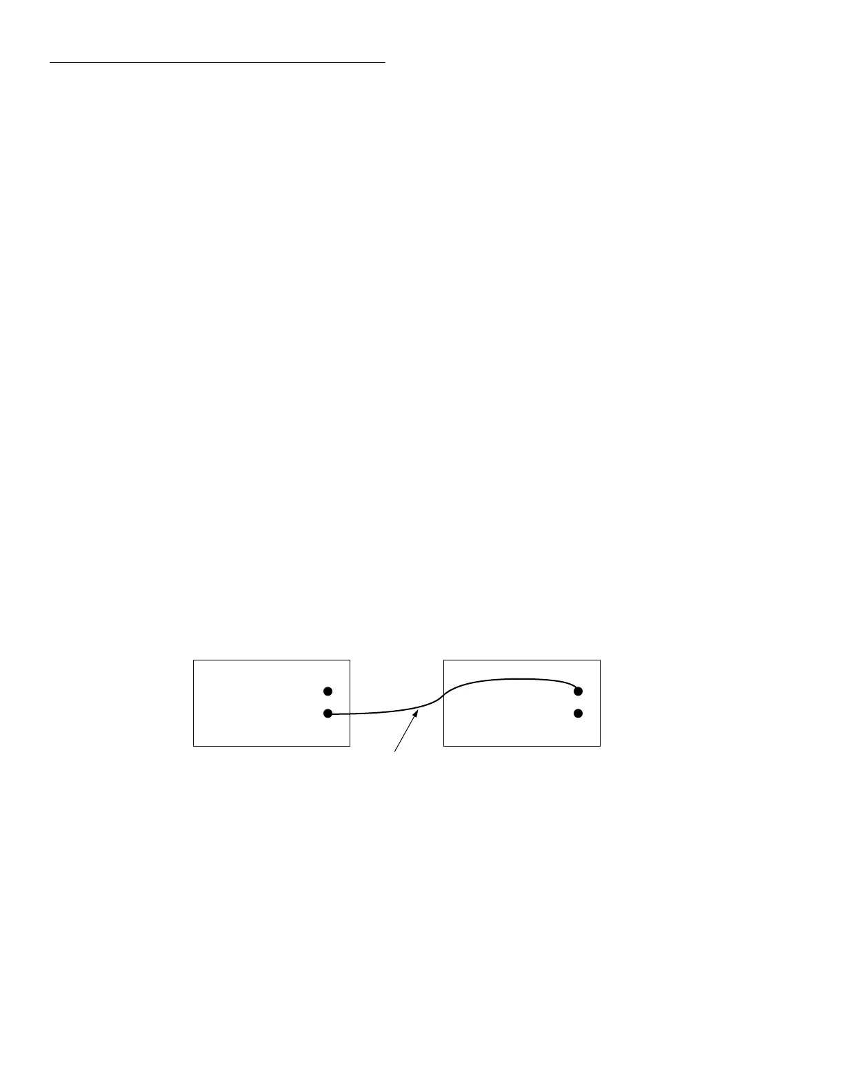
Figure 4-28
Trigger Link connections (semi-synchronous example)
Trigger
Link
7001 Switch System
Trigger Link
Cable
(8501)
IN
OUT
Line #1
Trigger
Link
Meter
IN
OUT
Semi-synchronous Trigger Link example
This example uses the same test system (Figure 4-19)
that was used for the Asynchronous Trigger Link Ex-
ample #1. However, triggering will be done using the
Semi-Synchronous mode. Trigger Link connections are
shown in Figure 4-28.
The two instruments are configured as follows:
Model 7001:
Scan List = 1!1-1!10,
Arm Layer:
Arm Spacing = Immediate*
Arm Count = 1*
Arm Trigger Control = Acceptor*
Scan Layer:
Scan Spacing = Immediate*
Number of Scans = 1
Scan Trigger Control = Acceptor*
Channel Layer:
Channel Spacing = TrigLink
Trigger Link Mode = Semi-Synchronous
Semi-Sync Line = #1
Trigger Control = Source*
Number of Channels = Use Scanlist Length*
* Indicates that the setting is the RESET (and factory) default
condition
Artisan Scientific - Quality Instrumentation ... Guaranteed | (888) 88-SOURCE | www.artisan-scientific.com
 Loading...

