3
Getting Started
3-1
3.1 Introduction
This section contains introductory information on us-
ing your Model 7001 Switch System. For detailed front
panel and IEEE-488 bus operation, refer to Sections 4
and 5 respectively.
The information in this section is arranged as follows:
3.2 Front and rear panel configuration:
Summarizes
the controls and display on the front panel of the
instrument.
3.3 Operation demo:
Demonstrates basic operation
using the built-in 40-channel multiplexer simula-
tor. Recommended for first time users.
3.4 Overview of scan process:
Provides a brief over-
view of the scan process.
3.5 Initial configuration:
Goes over some initial con-
figuration information that should be considered
before operating the instrument.
3.6 Front panel operation:
Demonstrates basic front
panel operation through the use of simple exam-
ples.
3.7 IEEE-488.2 and SCPI basics:
Discusses funda-
mental information concerning operation over
the IEEE-488 bus.
3.2 Front and rear panel
configurations
3.2.1 Front panel controls
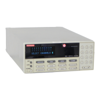
The front panel controls of the Model 7001 are shown
in Figure 3-1. This figure includes important abbreviat-
ed information that should be reviewed before operat-
ing the instrument. Notice that some of the controls are
dual-function, rocker-action type keys. These include
SCAN/CARD CONFIGURATION, DELETE/INSERT,
EXIT/ENTER and / .
3.2.2 Rear panel
The rear panel of the Model 7001 is shown in Figure 3-
2. This figure also includes important abbreviated
information that should be reviewed before operating
the instrument.
Artisan Scientific - Quality Instrumentation ... Guaranteed | (888) 88-SOURCE | www.artisan-scientific.com

 Loading...