Front Panel Operation
4-48
4.10 External triggering
The Model 7001 has BNC connectors on the rear panel
(see Figure 4-13) associated with external triggering.
The EXTERNAL TRIGGER input jack allows the Mod-
el 7001 to be triggered by other instruments and the
CHANNEL READY output jack allows the Model 7001
to trigger other instruments.
4.10.1 External trigger
The EXTERNAL TRIGGER input jack requires a fall-
ing-edge, TTL-compatible pulse with the specifications
shown in Figure 4-14.
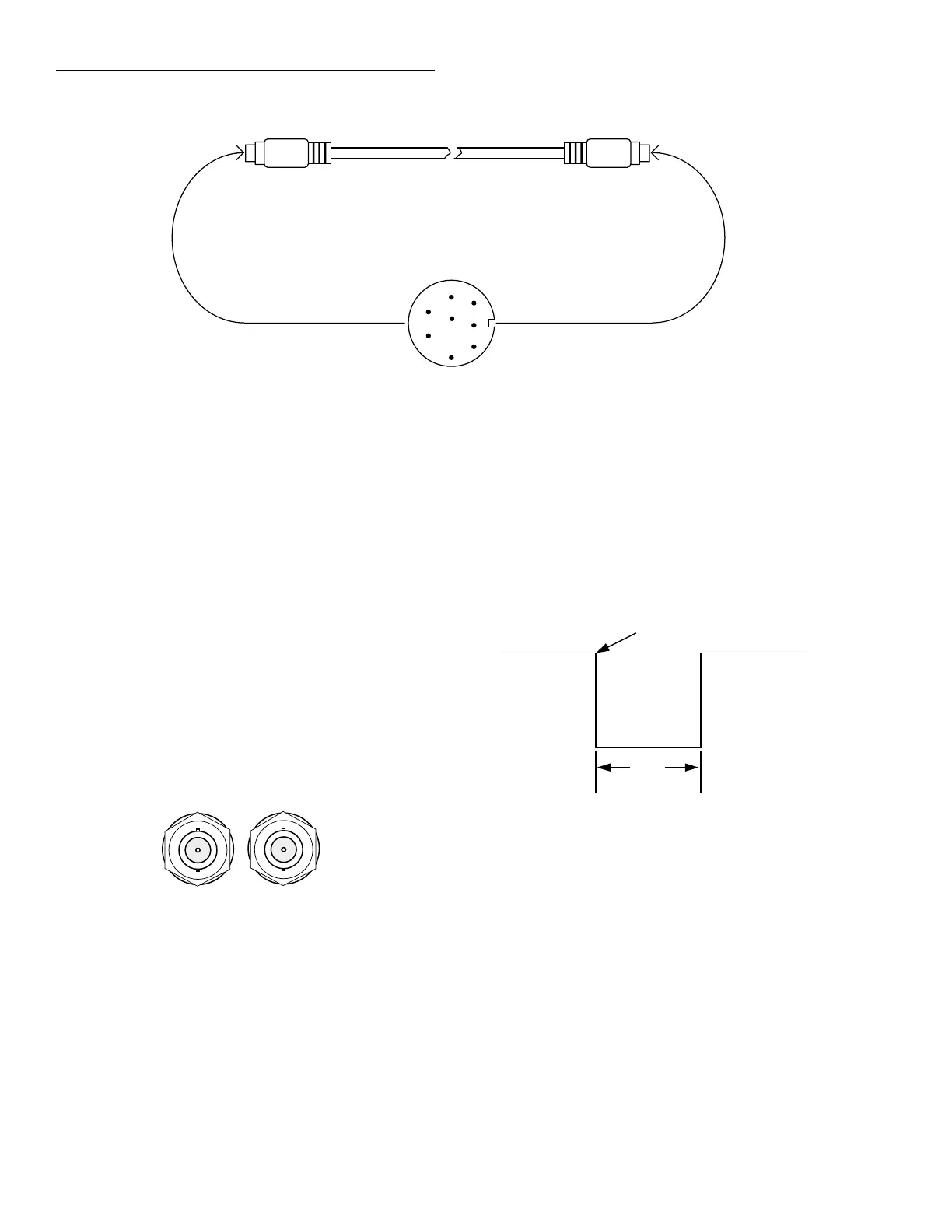
Figure 4-12
Digital I/O connections using trigger link cable
5
8
7
6
4
3
2
1
Cable Plug
Trigger Link Cable
1 = Digital Input
2 = N/C
3 = Voltage Input (up to 30V)
4 = Digital Output #1
5 = Digital Output #2
6 = Digital Output #3
7 = Digital Output #4
8 = Digital Common
Figure 4-13
External triggering connectors (BNC)
CHANNEL
READY
EXTERNAL
TRIGGER
In general, external triggers can be used as events to
control scan operation. In order for the Model 7001 to
respond to external triggers, the appropriate layers of
scan operation must be configured for it. Paragraph 4.8
explains how to program the three layers of the scan.
Figure 4-14
External trigger and asynchronous Trigger Link Input
pulse specifications
Triggers on
Leading Edge
TTL High
(2V-5V)
TTL Low
(≤0.8V)
2µs
Minimum
Artisan Scientific - Quality Instrumentation ... Guaranteed | (888) 88-SOURCE | www.artisan-scientific.com