Front Panel Operation
4-47
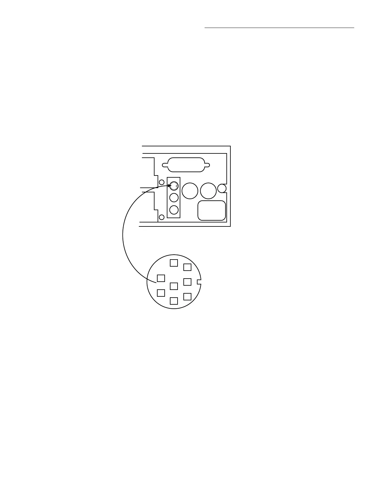
By hard-wiring an external circuit to an 8-pin micro
DIN female receptacle (see rear panel; Keithley Model
8501), you can use one complete Trigger Link cable for
the digital I/O connections. Figure 4-12 provides pin
identification for the Trigger Link cable when it is used
for the DIGITAL I/O port.
CAUTION
Trigger Link and the Digital I/O port
use the same type of connector. To
prevent possible damage, do not con-
nect the Digital I/O to the Trigger
Link. Also, when connecting an ex-
ternal circuit to the Digital I/O, take
care to not accidentally connect it to
the Trigger Link.
Figure 4-11
Digital I/O port
Digital I/O Port
5
8
7
6
4
3
2
1
1 = Digital Input
2 = N/C
3 = External Voltage Flyback
connection (up to 30V)
4 = Digital Output #1
5 = Digital Output #2
6 = Digital Output #3
7 = Digital Output #4
C
A
R
D
1
C
A
R
D
2
IEEE-488
DIGITAL I/O
CHANNEL
READY
EXTERNAL
TRIGGER
TRIGGER LINK
LINE
RATING
I
N
O
U
T
Artisan Scientific - Quality Instrumentation ... Guaranteed | (888) 88-SOURCE | www.artisan-scientific.com