Front Panel Operation
4-9
CHANNEL 1!1!1 = Slot 1, Row 1, Column 1
CHANNEL 2!3!6 = Slot 2, Row 3, Column 6
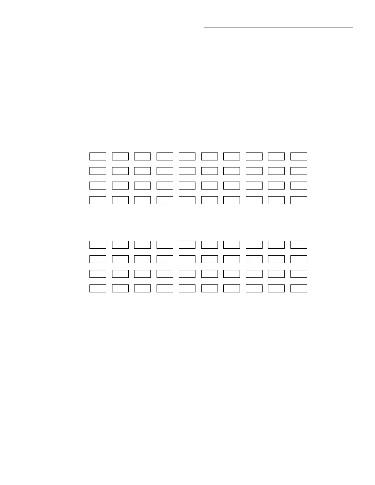
All mainframe channel assignments for matrix cards
are shown in Figure 4-7.
Figure 4-7
Channel assignments (matrix cards)
1 2 3 4 5 6 7 8 9 10
A. Slot 1 (Card 1)
1!1!1
1!2!1
1!3!1
1!4!1
1!1!2
1!2!2
1!3!2
1!4!2
1!1!3
1!2!3
1!3!3
1!4!3
1!1!4
1!2!4
1!3!4
1!4!4
1!1!5
1!2!5
1!3!5
1!4!5
1!1!6
1!2!6
1!3!6
1!4!6
1!1!7
1!2!7
1!3!7
1!4!7
1!1!8
1!2!8
1!3!8
1!4!8
1!1!9
1!2!9
1!3!9
1!4!9
1!1!10
1!2!10
1!3!10
1!4!10
1 2 3 4 5 6 7 8 9 10
B. Slot 2 (Card 2)
2!1!1
2!2!1
2!3!1
2!4!1
2!1!2
2!2!2
2!3!2
2!4!2
2!1!3
2!2!3
2!3!3
2!4!3
2!1!4
2!2!4
2!3!4
2!4!4
2!1!5
2!2!5
2!3!5
2!4!5
2!1!6
2!2!6
2!3!6
2!4!6
2!1!7
2!2!7
2!3!7
2!4!7
2!1!8
2!2!8
2!3!8
2!4!8
2!1!9
2!2!9
2!3!9
2!4!9
2!1!10
2!2!10
2!3!10
2!4!10
Examples : 1!2!4 = Slot 1, Row 2, Column 4
2!3!6 = Slot 2, Row 3, Column 6
CARD 1
CARD 2
Matrix cards:
Channels for a matrix card, such as the
Model 7012, are organized as row/column crosspoints
as shown in Figure 4-3B. When programming the Mod-
el 7001, you need to designate the slot in which the card
is installed. Thus, combining the slot number with the
crosspoint coordinates (row/column) provides the
CHANNEL assignment for the mainframe. Slot, row,
and column are separated by exclamation points (!).
For the following examples, “CHANNEL” refers to the
programming channel assignment for the mainframe.
Artisan Scientific - Quality Instrumentation ... Guaranteed | (888) 88-SOURCE | www.artisan-scientific.com