Home
Keysight Technologies
Measuring Instruments
34420A
Keysight Technologies 34420A User Manual
5
of 1
of 1 rating
189 pages
Give review
Manual
Specs
To Next Page
To Next Page
To Previous Page
To Previous Page
Loading...
1
Quick Start
34
Keysight 34420A Service Guide
To Measur
e Resistance
Ranges: 1
W
, 10
W
, 100
W
, 1 k
W
, 10 k
W
, 100 k
W
, 1 M
W
Maximum r
esolution: 0.1 µ
W
(
on 1 ohm range
).
NOTE
Resistance measur
ements use offset comp
ensation. Offset compensation can be
d
isab
led if desired.
33
35
Table of Contents
Safety Symbols
3
Safety Considerations
4
Environmental Conditions
5
Waste Electrical and Electronic Equipment (WEEE) Directive 2002/96/EC
6
Product Category
6
Sales and Technical Support
6
The Front-Panel at a Glance
8
The Front-Panel Menu at a Glance
9
Display Annunciators
11
The Rear Panel at a Glance
12
In this Book
13
Table of Contents
15
Quick Start
26
To Prepare the Meter for Use
27
If the Meter Does Not Turn on
28
To Adjust the Carrying Handle
30
To Make Input Connections
31
To Measure Voltage
33
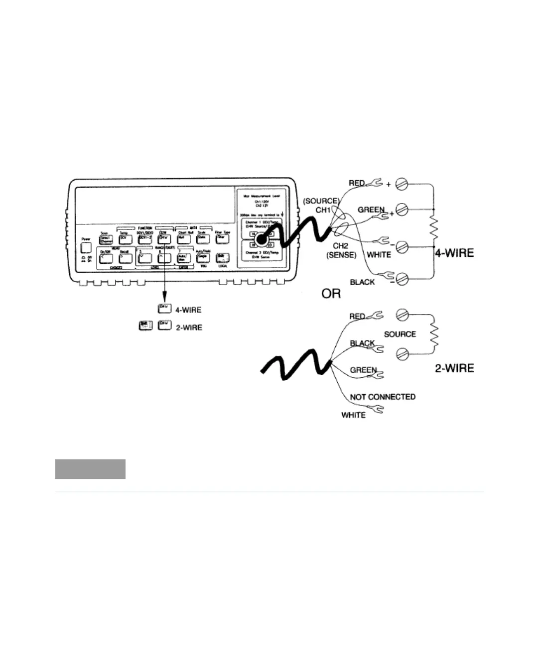
To Measure Resistance
34
To Measure Temperature with Thermistors
35
To Measure Temperature with Rtds
36
To Measure Temperature with Thermocouples
37
To Select a Range
38
To Set the Number of Digits
39
To Set the Integration Time
40
Front-Panel Display Formats
41
To Rack Mount the Meter
42
Front-Panel Operation
46
Front-Panel Menu Reference
47
A Front-Panel Menu Tutorial
51
To Select an Input Channel
60
To Select a Range
61
To Set or Change the Number of Digits
62
To Set the Integration Time
63
To Trigger the Meter
64
Null (Relative) Operation
65
To Use Math (Stats)
66
To Set the Number of Samples
68
Chart Output (Analog Output)
69
To Unsecure the Meter for Calibration
70
Calibration Procedures
75
Keysight Technologies Calibration Services
75
Calibration Interval
75
Time Required for Calibration
75
Automating Calibration Procedures
75
Recommended Test Equipment
77
Test Considerations
78
Performance Verification Tests
79
Self-Test
79
Quick Performance Check
80
Performance Verification Tests
80
Zero Offset Verification
81
Zero Offset Verification Procedure
81
Zero Offset Verification Procedure
82
Gain Verification
84
Gain Verification Procedure
84
Table 3-1 Table
84
Table 3-3 Table
85
MV and 10 MV Gain Verification (Optional)
86
MV and 10 MV Gain Verification Procedure
86
Table 3-5 Table
87
MV and 10 MV Gain Verification Procedure
87
Injected Current Verification (Optional)
88
Injected Current Verification Procedure
88
Chart Output Verification (Optional)
89
Chart Output Verification Procedure
89
Calibration Security Code
91
To Unsecure the Meter Without the Security Code
92
Calibration Count
94
Calibration Message
95
Calibration Procedure
96
Aborting a Calibration in Progress
97
Zero Calibration
98
Zero Calibration Procedure
98
Gain Calibration
99
Gain Adjustment Considerations
99
Gain Calibration Procedure
99
Table 3-7 Table
100
Table 4-2 Table
100
Gain Verification Procedure
100
Gain Calibration Procedure
100
Injected Current Calibration (Optional)
101
Internal Temperature Reference Calibration (Optional)
103
Chart Output Calibration (Optional)
104
Error Messages
105
Calibration Error Messages
107
Theory of Operation
110
Block Diagram
110
Input and Protection
112
Function Switching
114
DC Amplifier
115
Amplifier Gain
115
Ohms Current Source
117
2-Wire or 4-Wire Resistance Measurements
117
A-To-D Converter
120
Configuration Data Shift Register
122
Injected Current Compensation
122
Chart Recorder Output
122
Floating Logic
123
Earth-Referenced Logic
126
Power Supplies
127
Front Panel
128
Service
129
Operating Checklist
130
Service Operating Checklist
130
Types of Service Available
131
Repackaging for Shipment
133
Electrostatic Discharge (ESD) Precautions
134
Surface Mount Repair
135
To Replace the Power-Line Fuse
136
Input Connector
137
Cleaning the Connector Contacts
138
Troubleshooting Hints
139
Self-Test Procedures
141
Power-On Self-Test
141
Complete Self-Test
141
Performing Individual Tests
141
Replaceable Parts
145
To Order Replace Parts
146
Backdating and Part Changes
146
Input Connector Replaceable Parts
147
34420-66501 Main PC Assembly
148
34420-66502 Display and Keyboard PC Assembly
164
34420A Mainframe
166
Manufacturer's List
167
Backdating
169
Schematics
171
Mechanical Disassembly
172
34420-66501 Component Locator
173
34420-66502 Component Locator
174
Block Diagram
175
Input and Protection Schematic
176
Function Switching Schematic
177
DC Amplifier Schematic
178
Ohms Current Source Schematic
179
A/D Converter Schematic
180
Configuration Data Shift Registers Schematic
181
Floating Logic Schematic
182
Earth Referenced Logic Schematic
183
Power Supply Schematic
184
Display and Keyboard Schematic
185
Characteristics and Specifications
187
5
Based on 1 rating
Ask a question
Give review
Questions and Answers:
Need help?
Do you have a question about the Keysight Technologies 34420A and is the answer not in the manual?
Ask a question
Keysight Technologies 34420A Specifications
General
Brand
Keysight Technologies
Model
34420A
Category
Measuring Instruments
Language
English
Related product manuals
Keysight Technologies 34921A
67 pages
Keysight Technologies 34980A
149 pages
Keysight Technologies 34923A
67 pages
Keysight Technologies B1505A
266 pages
Keysight Technologies E5061B
121 pages
Keysight Technologies M9370A
76 pages
Keysight Technologies N9030B
617 pages
Keysight Technologies P Series
673 pages
Keysight Technologies UXA N9040B
6 pages
FieldFox N9914A
756 pages
FieldFox N9938A
756 pages
FieldFox N9917A
756 pages