4 Theory of Operation
112 Keysight 34420A Service Guide
Input and Protection
This discussion refers to the Chapter 8, "Input and Protection Schematic" and the
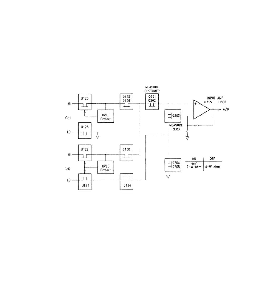
simplified input diagram below. Each input terminal is protected against high
energy transients (e.g., electrostatic discharge) through E101 through E104, L101
through L106 and C101 through C106.
The Channel 1 HI input signal is connected from the input terminal through the
solid state switch U120 and FETs Q125 and Q126. (Similar switching
arrangements exist in the Channel 2 HI and LO input paths.) U121A/B controls
the state of the switches. In normal operation on all ranges except the 100 V
range, the switches are turned on by a bit from the Shift Registers. The Channel 1
HI overload circuit consists of Q121, Q122, Q123, and Q124 along with U121B.
This forms an overload clamp circuit that opens the input protection switch U120
if the input exceeds ± 14 Vdc. A similar circuit exists for the Channel 2 HI input.
On the 100 V Range, relay K102 is closed to connect the input signal to the
Function Switch through the 100:1 high voltage divider resistor network U102A.
Both K101 and K102 are driven by relay driver U150 (on the Function Switching