Keysight N5221A/22A Service Guide 7-49
Repair and Replacement Procedures
Removing and Replacing the A38–A41 Bias Tees
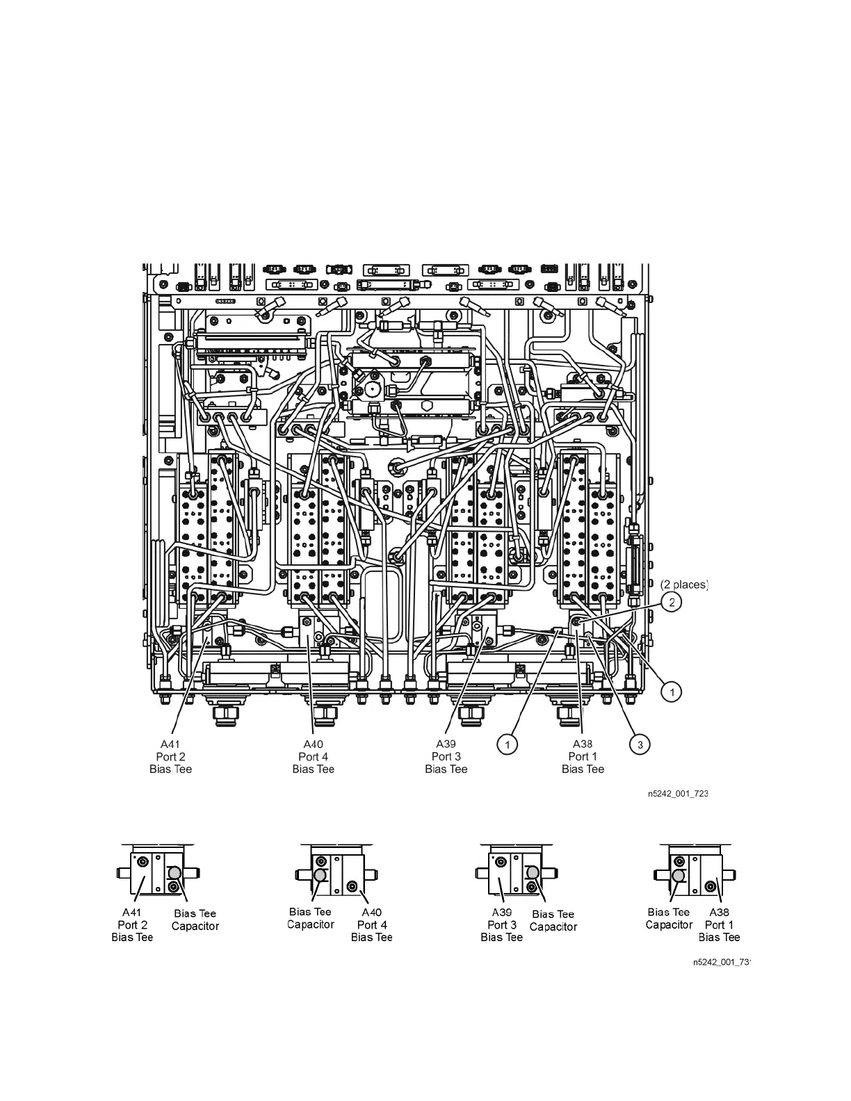
2. As shown in Figure 7-22, position the bias tees on the attenuator brackets
so that the port 1 and port 3 bias tees capacitors face each other. The port
2 and port 4 bias tee capacitors should also face each other.
3. Perform the post-repair adjustments, verifications, and performance tests
that pertain to this removal procedure. Refer to Table 7-2 on page 7-60.
Figure 7-21 A38 through A41 Bias Tees Removal
Figure 7-22 Orientation of Bias Tee Capacitors