3-18 Keysight N5221A/22A Service Guide
Tests and Adjustments
Preliminary Checks
3-
6. To provide a good reference, hold the test cable in a straight line
perpendicular to the front panel of the network analyzer.
7. Press RESPONSE , then .
8. Wait for the analyzer to average the measurement 50 times (approximately
two seconds).
9. To normalize the data trace: press MARKER/ANALYSIS , then
, t h e n , t h e n , t h e n E N T R Y .
10.Slowly make a 180 degree bend in the middle of the cable and hold it in
that position.
11.For each trace: press RESPONSE , then .
The Scale Per Division box will appear directly above the display. Set the
Scale Per Division for optimum viewing as shown in Figure 3-7.
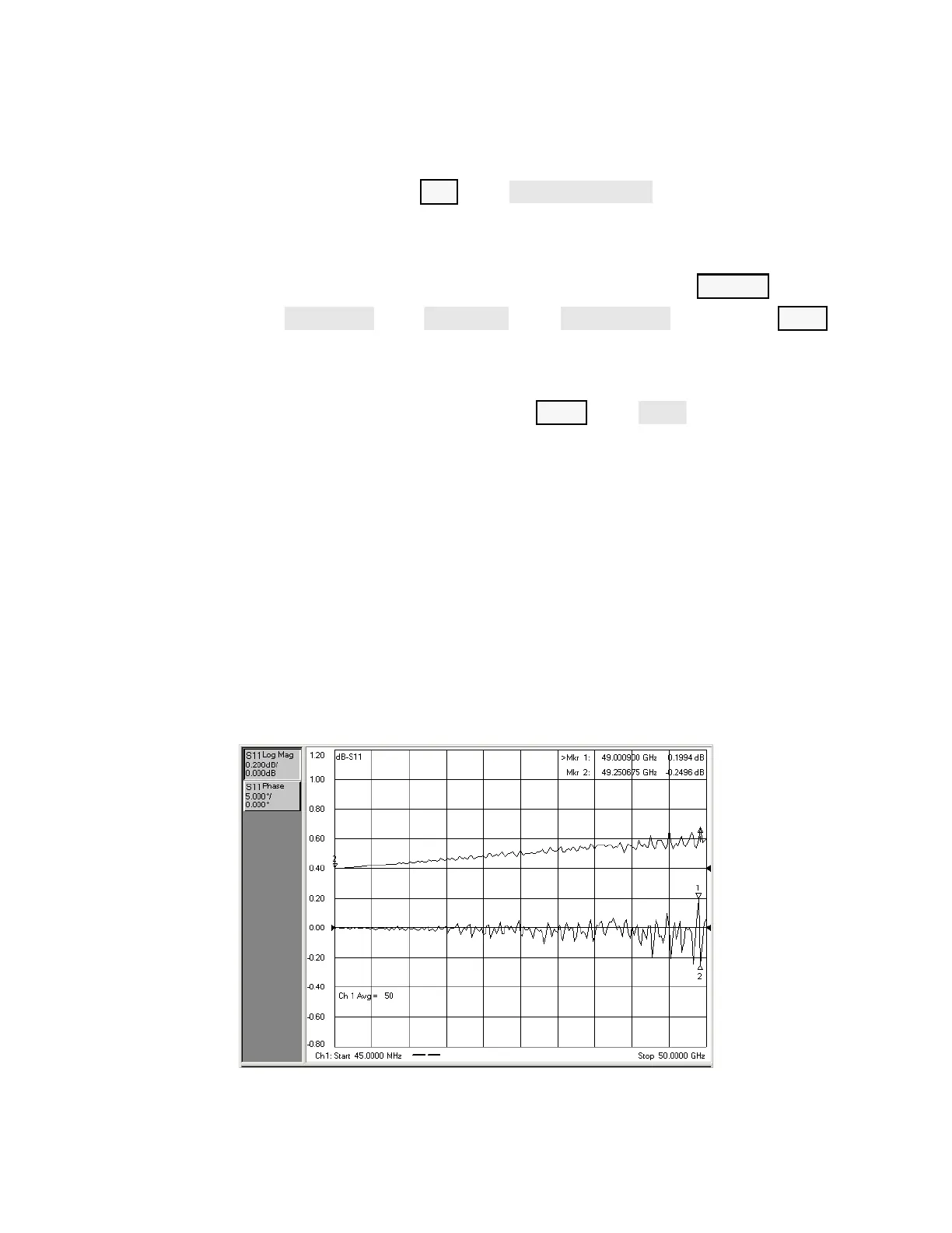
12.Place a marker on the largest deflection that goes above the reference line
and is within the cable’s specified frequency range. For a typical response
of cable magnitude and phase stability, see Figure 3-7.
13.Place a marker on the largest deflection that goes below the reference line
and is within the cable’s specified frequency range.
In this S
11
measurement, the displayed trace results from energy being
propagated down the cable and reflected back from the short. Therefore,
the measured deflection value must be divided in half to reach the correct
value.
Figure 3-7 Typical Cable Magnitude and Phase Stability Response