Installation and Service Guide N5250-90001 2-5
PNA Series Microwave Network Analyzer System
N5250A
System Description
Basic System Configurations
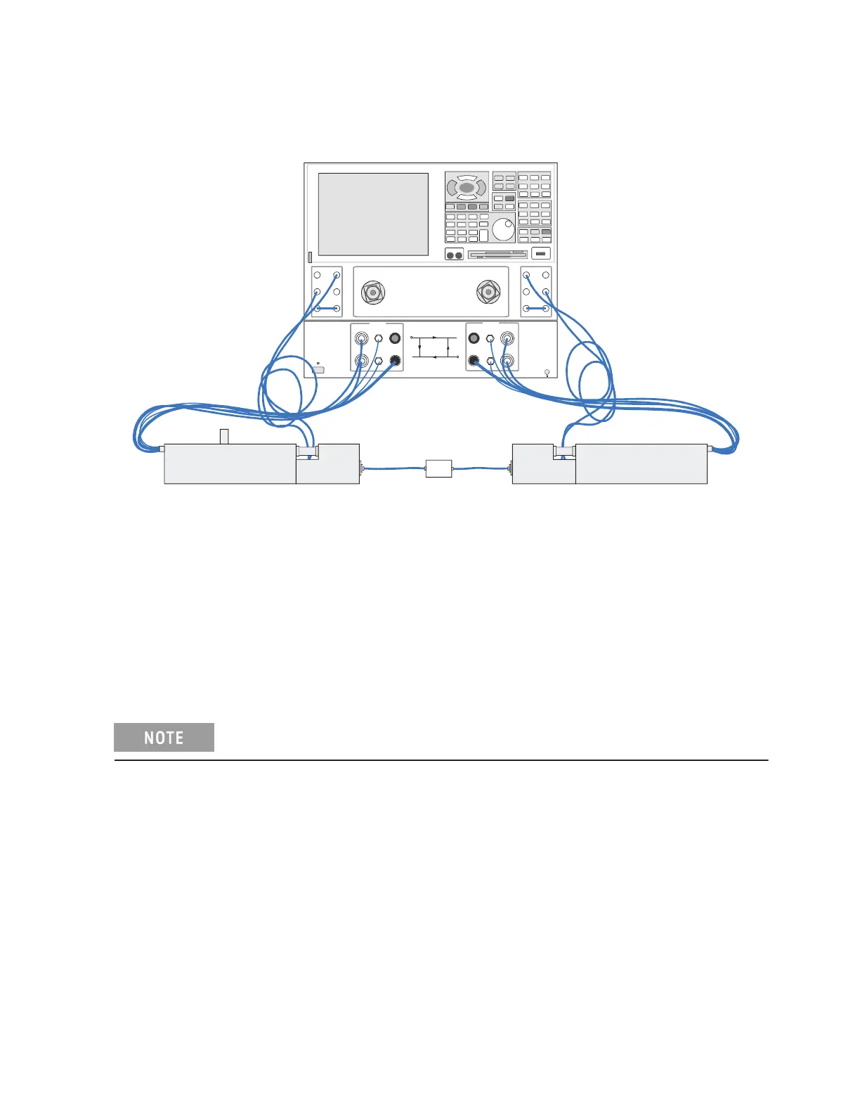
Figure 2-2
Coaxial Measurement Configuration
Wafer Probe Measurement
This configuration is used for on-wafer testing; each test port is connected (through a 1.0 mm
coaxial cable, or through an adapter and another type of coaxial cable) to a wafer test probe.
Contact the manufacturer of the wafer probe station and an Keysight office for information
on the cables and adapters needed to connect the test head modules to the wafer probe
station (refer to “General Safety Considerations” on page 1- 2. In this configuration, the test
head modules are placed on X-Y positioners that are mounted to the wafer probe station.
The wafer probe measurement configuration is not documented in this manual.
For information about probing equipment and accessories, contact:
For additional information on DUT bias connections, refer to Table 4-3 on page 4-5,
Figure 4-1 on page 4-6, and Figure 4-2 on page 4-6.
Cascade Microtech, Inc.
2430 NW 206th Avenue
Beaverton, Oregon 97006
USA Toll-free telephone: (800) 550-3279
Telephone: (503) 601-1000
Fax: (503) 601-1002
Web site www.cascademicrotech.com
Email: sales@cmicro.com
Port 2
RCVR
B IN
CPLR
ARM
SOURCE
OUT
CPL R
THRU
SOURCE
OUT
RCVR
R2 IN
Reference 1
Port 1
RCVR
A IN
CPLR
ARM
SOURCE
OUT
CPLR
THRU
SOURCE
OUT
RCVR
R1 IN
E8361A Network Analyzer 45 MHz to 67 GHz
0
1
N5260A
Millimeter Head C ontroller
LINE
Port 1
Port 1
Port 2
Port 2
RF OUT
RF O UT
LO OUT
LO OUT BIAS
BIAS
2 AMP FUSE
2 AMP F USE
R1 IF
R2 IF
A IF
B IF
PNA Series
Network Analyzer with
Options 014, 080, 081,
UNL, and H11
N5260A
Millimeter-Head
Controller
Left Test Head
DUT
Right Test Head
n5250_001_303
Required
1.0 mm
Test P ort
Cable
Optional
Cable
 Loading...


