Installation and Service Guide N5250-90001 3-11
PNA Series Microwave Network Analyzer System System Installation
N5250A PNA, Controller, and Test H
ead Module Interconnections
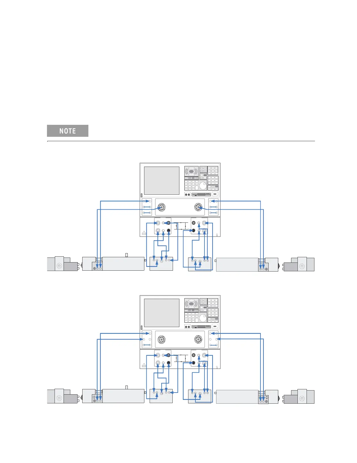
Front Panel Cabling
The front-panel interconnections between
the N5260A millimeter head controller and the test
head modules are shown in Figure 3-3, Figure 3-4, and Figure 3-6.
The test head modules are placed on the work surface in front of the PNA and head controller as
shown. When the test head modules are facing each other like this, the Port 1 connector faces
the Port 2 connector.
Refer to “Sequence of Test Head Module Connections” on page 3-13 for power supply
connections to the test head modules.
The order in which cables are connected to a test head module is
significant; see “Sequence of Test Head Module Connections” on page 3-13.
Figure 3-3 N5250C Standard Configuration
Figure 3-4 N5250C Option 017/018 Configuration
Port 2Port 1
Reference 2
Port 2
RCVR
B IN
CPLR
ARM
SOURCE
OUT
CPLR
THRU
SOURCE
OUT
RCVR
R2 IN
Reference 1
Port 1
RCVR
A IN
CPLR
ARM
SOURCE
OUT
CPLR
THRU
SOURCE
O UT
RCVR
R1 IN
E8361A Network Analyzer 45 MHz to 67 GH z
0
1
N5260A
Millime ter-Head Con troller
LINE
Por t 1
Port 1
Port 2
Port 2
2 AMP FUSE
2 A MP FU SE
RCVR B IN
RCVR A IN
RC R AV
RINF
RC R BV
RINF
RF IN
RF
IN
Ref IF
Ref IF
Bias
LO OUT
R2 IF
RF OUT
RF OUT
BIAS
R1 IF
A IF
B IF
BIAS
LO UTO
LO IN
Test IF
Bias
LO IN
Test IF
n5250_001_305
Port 2Port 1
Reference 2
Port 2
RCVR
B IN
CPLR
ARM
SOURCE
O UT
CPLR
THRU
SOURCE
O UT
RCVR
R2 IN
Reference 1
Port 1
RCVR
A IN
CPLR
ARM
SOURCE
O UT
CPLR
THRU
SOURCE
OUT
RCVR
R1 IN
E8361A Network Analyzer 45 MHz to 6 7 GHz
0
1
N5260A
Millim eter-Head C ontroller
LIN E
Port 1
Port 1
Por t 2
Port 2
2 AM P FUS E
2 AMP FUSE
RCVR B IN
RCVR A IN
SOURCE OUT
SOURCE OUT
RC R AV
RINF
RC R BV
RINF
RF IN
RF
IN
Ref IF
Ref IF
Bias
LO OUT
R2 IF
RF OUT
RF OUT
BIAS
R1 IF
A IF
B IF
BIAS
LO UTO
LO IN
Test IF
Bias
LO IN
Test IF
n5250_001_306
 Loading...


