Installation and Service Guide N5250-90001 3-13
PNA Series Microwave Network Analyzer System System Installation
N5250A PNA, Controller, and T
est Head Module Interconnections
Sequence of Test Head Module Connections
Use a 57 N-cm (5 in-lb) torque wrench to tighten the SMA connectors and a 90
N-cm (8 in-
lb) torque wrench to tighten the 1.85 mm and 3.5 mm connectors.
The connectors on the backs of the test head mo
dules are very closely spaced. Attaching
cables to these connectors is e
asiest if they are attached in the following sequence as
illustrated in Figure 3-7.
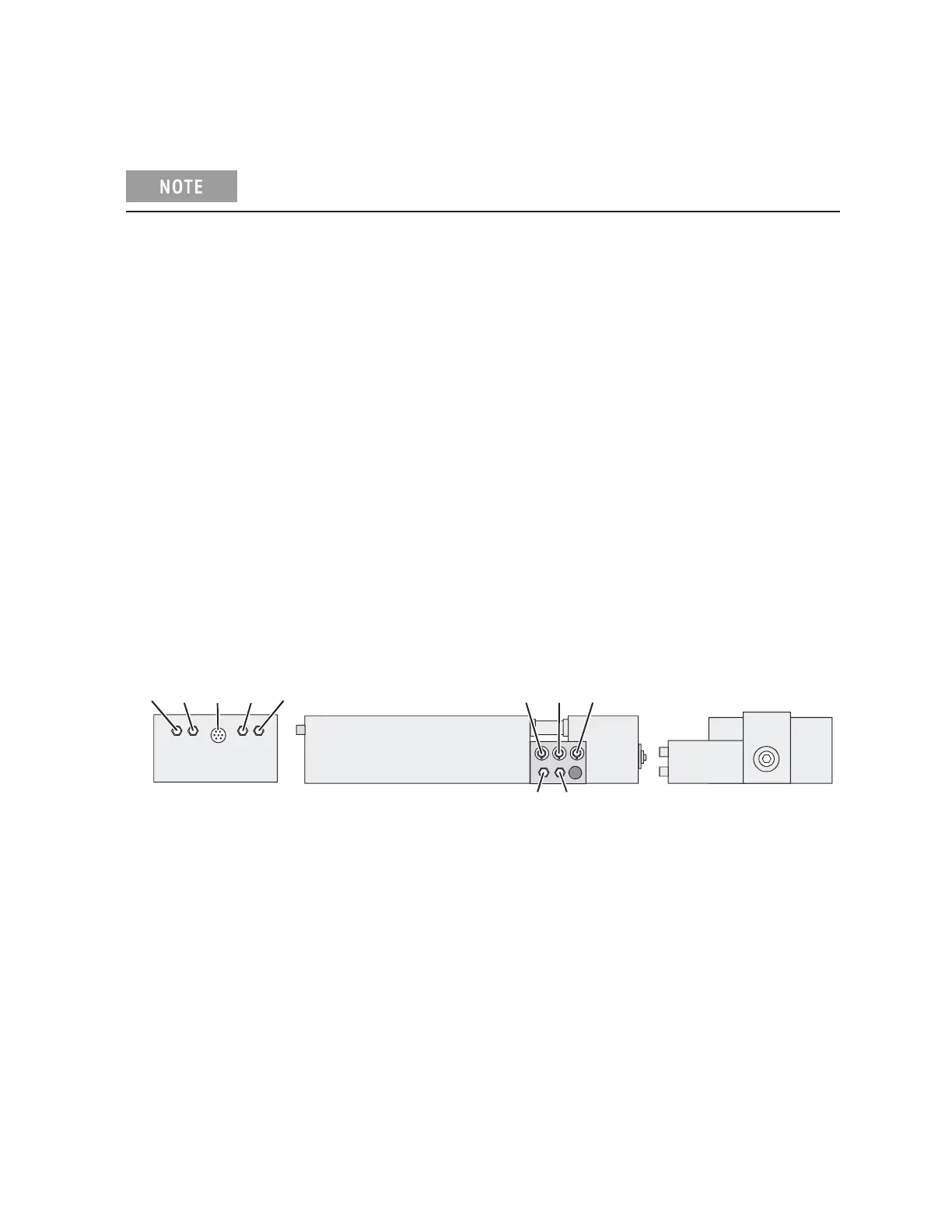
Figure 3-7 Test Head Module Cabling Sequence
n5250_001_308
1
9
7
2
8
6
5
4
3
10
1. BIAS; +12V @ 1.5A
2. RF INPUT; SMA connector, 11.17-19.33 GHz @ +5 to +13 dBm
3. LO INPUT; SMA connector,
8.37-14.5 GHz @ +5 to +13 dBm
4. REF IF; SMA connector
5. TEST IF; SMA connector
6. RCVR A or B; 1.85 mm co
nnector
7. RF IN (Port 1 or 2); 1.85 mm connector
8. Ground Unit (GNDU); sub mini-triax connector (N5250C O
ptions 017 and 018)
9. SENSE; sub mini-triax connector (N5250C Optio
ns 017 and 018)
10. FORCE; sub mini-triax connector (N5250C Options 017 and 018)
 Loading...


