80 Chapter 3
Theory of Operation
Waveform Playback
front panel trigger out connector. There are 16 marker output selections for the LXI
trigger bus; LAN 0–7 and LXI 0–7.
Markers can be set in the sequencer to be at any point in the data with a positive or
negative polarity. Marker widths, except those derived from waveform memory, can
be set in increments of the SYNC clock (-8 to 247 clocks). The marker delay
function uses the input value to calculate the delay to the nearest 1/4 SYNC clock
cycle. The sequencer is capable of outputting nine markers, which can be
multiplexed to the four marker outputs. The Sequence Start, Sequence Gate,
Scenario Repeat, and three software markers are only available through the
programmatic interfaces.
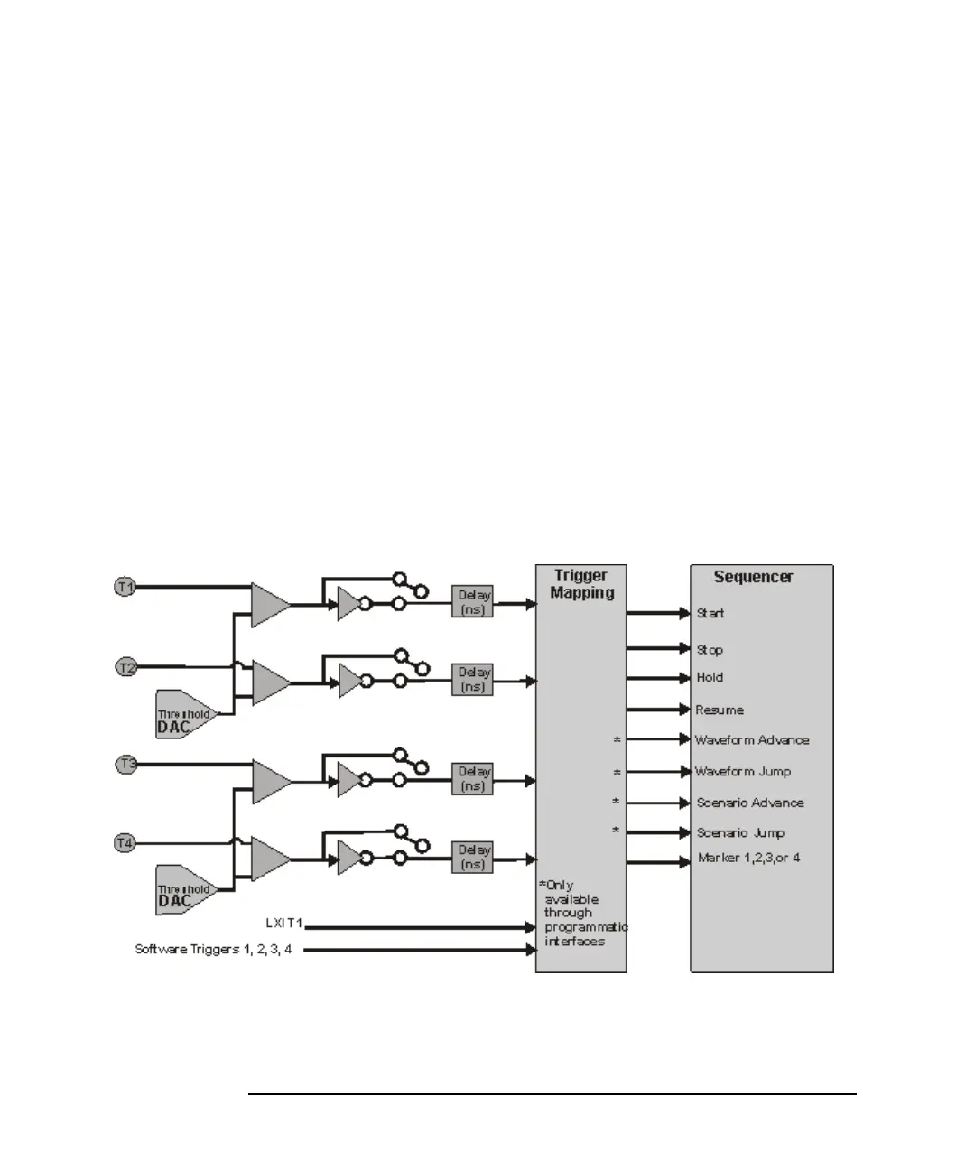
Triggers
The AWG module has five front panel trigger input connector, a rear panel LXI
trigger bus, and triggering through the LAN line. All triggers passing through the
LXI trigger bus and the LAN line are executed through the LXI T1 trigger.
Figure 3-6 Trigger Block Diagram