Chapter 2 43
Basic Operation
Using the Graphical User Interface
Creating and Playing a Sequence
1. Connect the channel 1 positive (+) output to the spectrum analyzer RF input
connector.
2. Open the user interface by double-clicking the N8241A icon placed on the
desktop during installation.
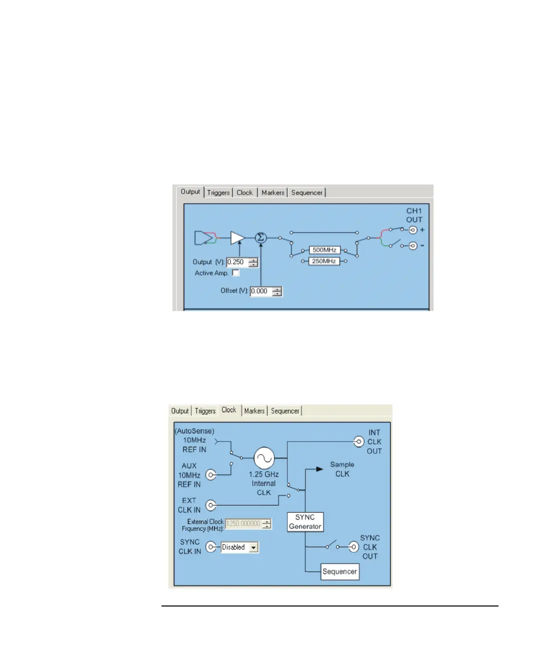
3. Select the Output tab and connect a single-ended signal conditioning path to
CH1 OUT (+) (click on the node that you want to connect).
The connection will automatically enable differential mode. Click on the
negative (-) node to enable single-ended mode.
.Notice that the default gain value was 0.500 volts. Once you select single-ended
mode, the value drops to 0.250 volts. These are maximum values for the modes
indicated.
4. Select the Clock tab and confirm that the (AutoSense) 10MHz REF IN is
configured correctly.