Chapter 3 91
Theory of Operation
Multiple Module Synchronization
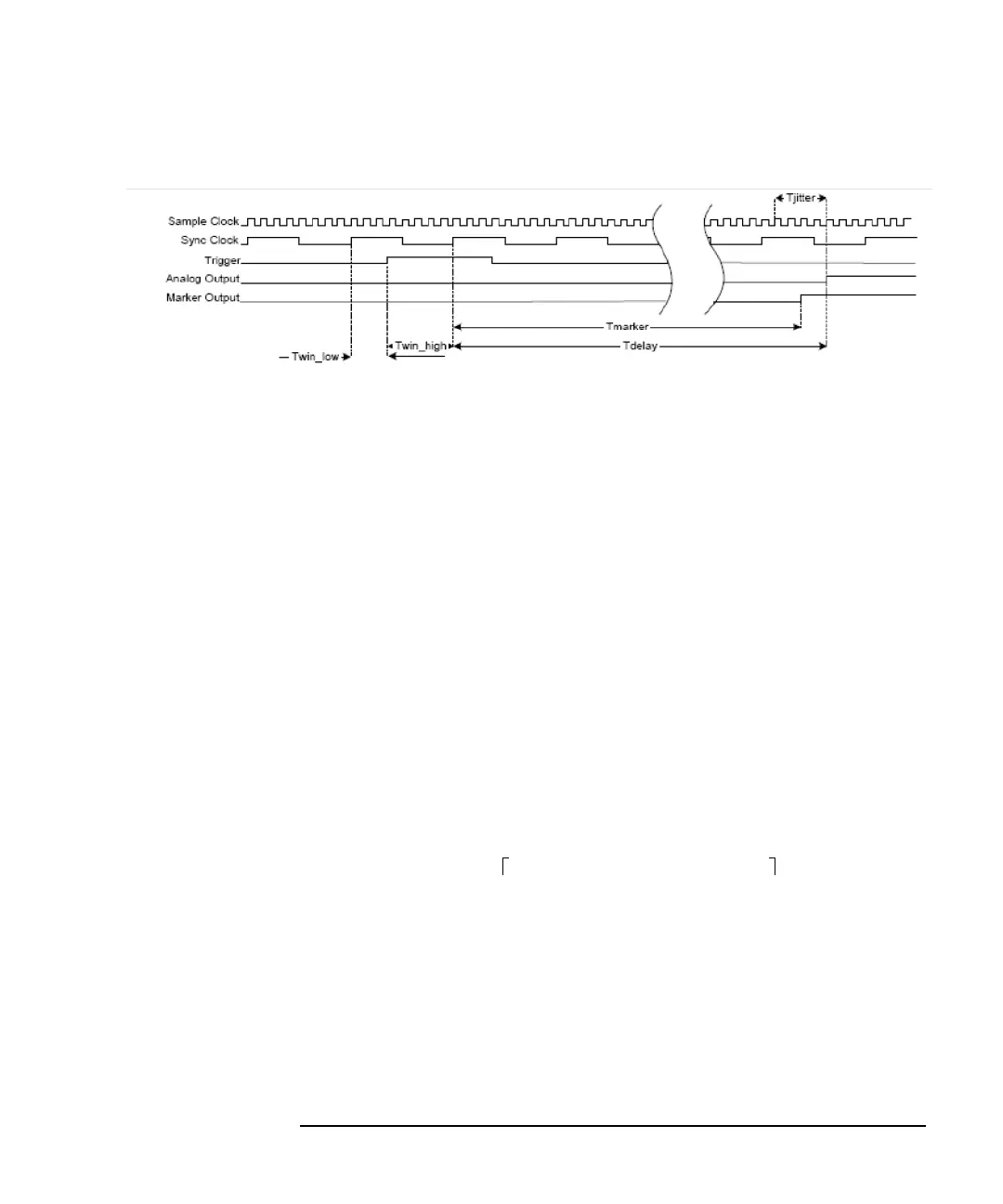
Figure 3-10 Multiple Module Synchronous Trigger Timing Diagram
Cable Length and Skew
The cabling requirements are as follows:
Sample Clock
Skew less than 10 mm between modules. The absolute SYNC cable length is
given by the
Equation as a function of the Sample clock frequency:
Sample Clock Skew Formula
Expressed in mm, where n is an arbitrary integer and f is the sample clock
frequency in MHz.
It should be noted that n is the number of 1/2 SYNC clock cycles of total delay
between the modules.
This can also be expressed in terms of delay:
Expressed in nanoseconds, where n is an arbitrary integer and f is the sample
clock frequency in MHz.
For the external Sample clock the formulas apply over the frequency range of
625 MHz to 1.25 GHz
Marker and Trigger Cables
The Marker Out to Trigger In cable should be less than 305 mm (12 in). With the
1.25 GHz internal clock, the trigger is falling edge triggered.
Length n( 686 1250MHz()f)⁄×× 394–[]=
Cabledelay n 3.29 1250MHz()f⁄××()1.89–=