7Tutorial
188 Keysight E3633A and E3634A User’s Guide
Connecting the Load
Output isolation
The output of the power supply is isolated from chassis ground. Any output
terminal may be grounded, or an external voltage source may be connected
between any terminal output and ground. However, output terminals must be
kept within ±60 Vdc when metal shorting bars without insulation are used to
connect the (+) output to the (+) sense and the (-) output and the (-) sense
terminals or ±240 Vdc of ground when metal shorting bars without insulation are
either replaced with insulated conductors or they are removed from the terminals
so there is no operator access to the output conductors without insulation. A
chassis ground terminal is provided on the front panel for convenience.
Multiple loads
When connecting multiple loads to the power supply, each load should be
connected to the output terminals using separate connecting wires. This
minimizes mutual coupling effects between loads and takes full advantage of the
low output impedance of the power supply. Each pair of wires should be as short
as possible and twisted or shielded to reduce lead inductance and noise pick-up.
If a shield is used, connect one end to the power supply ground terminal and leave
the other end disconnected.
If cabling considerations require the use of distribution terminals that are located
remotely from the power supply, connect output terminals to the distribution
terminals by a pair of twisted or shielded wires. Connect each load to the
distribution terminals separately.
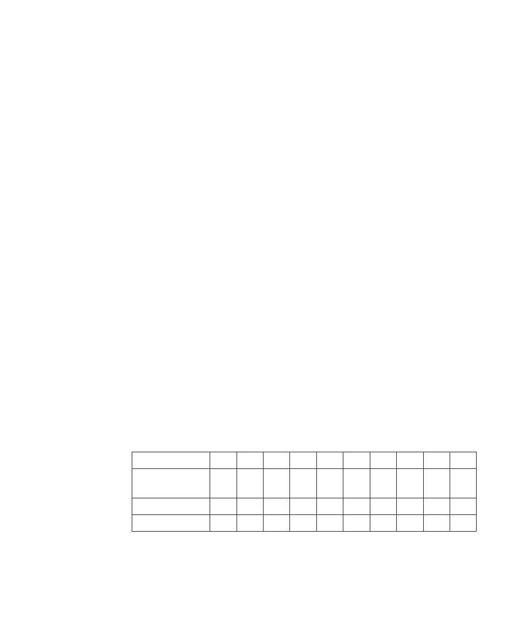
Table 7-1 Wire rating
AWG 10121416182022242628
Suggested maximum
Current (amps)
[a]
[a] Single conductor in free air at 30 °C with insulation
40 25 20 13 10 7 5 3.5 2.5 1.7
mΩ/ft 1.00 1.59 2.53 4.02 6.39 10.2 16.1 25.7 40.8 64.9
mΩ/ft 3.3 5.2 8.3 13.2 21.0 33.5 52.8 84.3 133.9 212.9