Features and Functions 2
Keysight U1731C/U1732C/U1733C User’s Guide 51
Measuring impedance (Z)
All circuit components, resistors, capacitors, and inductors have parasitic
components. These include, for example, unwanted resistance in capacitors,
unwanted capacitance in inductors, and unwanted inductance in resistors. Thus,
simple components should be modeled as complex impedances.
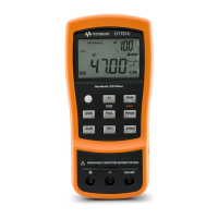
Set up your LCR meter to measure impedance as shown in Figure 2-9.
1 Press to power on the LCR meter.
2 Press to select a suitable test frequency, and press to select
impedance measurement.
Figure 2-8 Impedance measurement with theta
3 Insert a component into the component socket or connect the test clip to the
component leads as required.
4 Press to change the secondary display measurement (D, Q, or θ).
5 Read the displays.
To learn more about impedance measurement theories, refer to the Impedance
Measurement Handbook. This document can be downloaded from our website
at http://www.keysight.com/find/lcrmeters.

 Loading...
