10
Assemble units as described herein only. To do otherwise
may result in instability. All screws, nuts and bolts must be
tightened securely and must be checked periodically after
assembly. Failure to assemble properly, or to secure parts
may result in assembly failure and personal injury.
Tributaire™ Collection - Lecterns
Assembly Instructions
upright
mounting
head
1
/ -20 nylon
4
11
/ -20 x 20 /”
44
draw bolt
mounting
head
1
/ -20 nylon
4
cap lock nut
upright
11
/ -20 x 20 /”
44
draw bolt
mounting
head
mounting
head cover
#- x /”83
orx
3
8
at head screw
upright
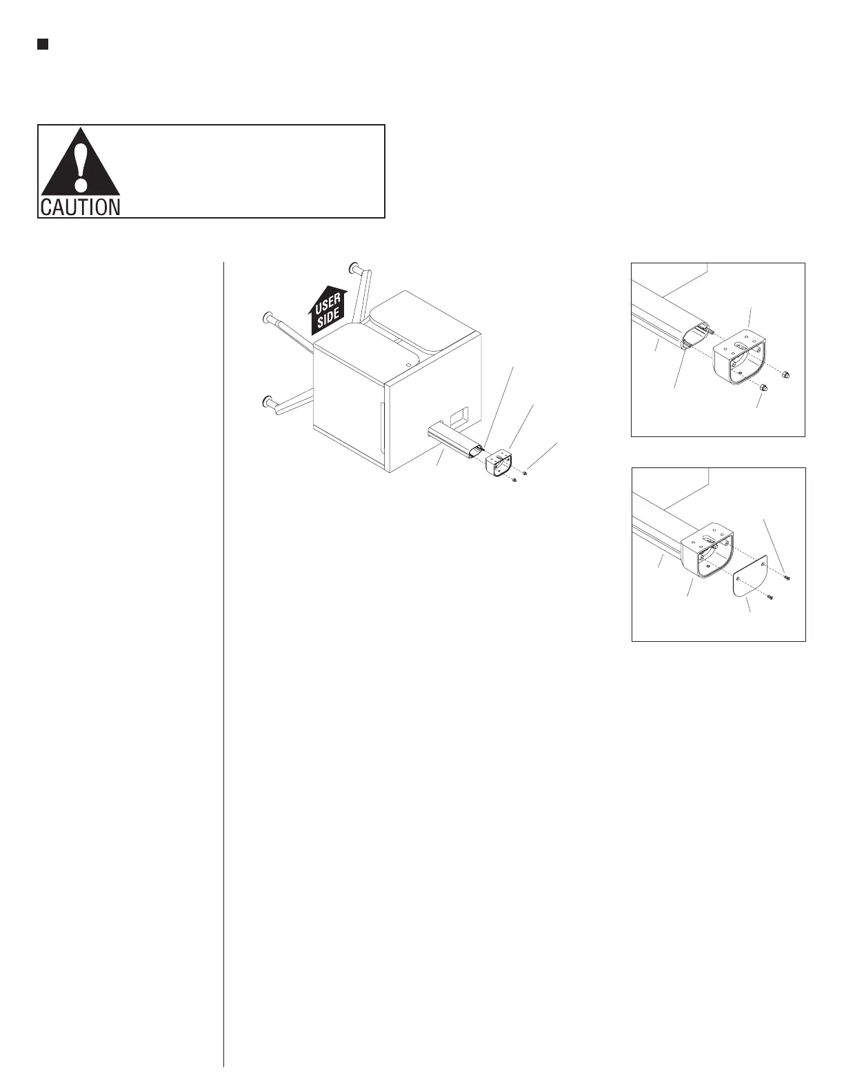
6. Position the mounting head next to
the upright of the base assembly as
illustrated with the mounting head’s
front mounting holes facing the front,
user side of the base assembly. Place
the mounting head against the top
of the upright, aligning the head’s
bottom mounting holes onto the
upright’s draw bolts, where the
lock nuts were removed in the last
step. Under the base, and one
1
/
4
-20 x 20
1
/
4
” draw bolt at a time,
press on the bottom of the draw bolt
from under the base upright, and
loosely twist a previously removed
1
/
4
-20 nylon cap lock nut onto the
draw rod threads at the top, in the
mounting head. Repeat this process
with the second draw bolt and
second
1
/
4
-20 lock nut. Then, using
a T-30 Torx bit socket on a wrench at
the bottom, and a
7
/
16
” socket on an
extension, with socket wrench on the
top, tighten both nuts to their draw
bolts securely (Figure 10 & Detail L).
7. Place a mounting head cover above
the mounting head and secure using
two #8-32 x
3
/
8
” Torx flat head screws
(Detail M).
8. Carefully turn the X-base assembly
to the upright position on the floor.
9. Proceed to “Perforated Steel Panel
Installation” instructions on the next
page.