22
Assemble units as described herein only. To do otherwise
may result in instability. All screws, nuts and bolts must be
tightened securely and must be checked periodically after
assembly. Failure to assemble properly, or to secure parts
may result in assembly failure and personal injury.
Tributaire™ Collection - Lecterns - Accessories
Assembly Instructions
1
modesty panel
mounting plate
modesty
panel
worktop support
platform
Detail A - (underside view)
modesty
panel
mounting
bracket
1
/ -20 nylon
4
insert cap
lock nut
1
/
4
”
washer
modesty panel
/ -16 x /”
Allen button head
screw
3
/”
8
bearing
3
/”
8
cupholder
cupholder
mounting
bracket
worktop
Detail C - (underside view)
cupholder
worktop
Detail B - (underside view)
3
/”bearing
8
3
/”bearing
8
cupholder
swivel slot
(right-hand)
Accessories Overview
Note: If the lectern being
assembled requires a modesty
panel, proceed to “Modesty Panel
Installation” instruction below. If
the lectern requires a cupholder,
proceed to “Cupholder Installation”
instructions below. If the lectern
does not require any accessories,
but is a screw-adjustable height
lectern and requires adjustments,
proceed to the next page. If
the lectern does not need any
adjustments but has a Mini-Tap
power module, proceed to page 24,
otherwise move the lectern to the
final location of use.
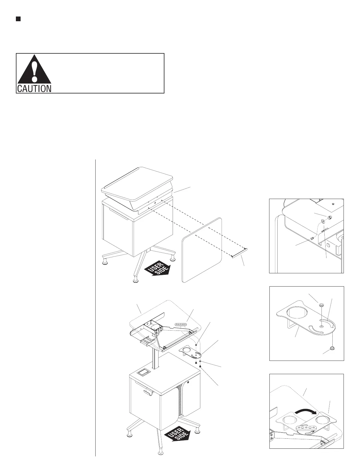
Modesty Panel Installation
(optional)
1. At the back, non-user side of the
lectern, align the mounting holes
of the modesty panel with the
mounting holes on the back of the
worktop support platform. Then,
press the threaded studs of through
the modesty panel mounting plate
through the modesty panel and the
mounting holes in the back of the
worktop support platform. From
under the support platform, secure
the modesty panel to the platform
by threading a
1
/
4
-20 nylon lock
nut and washer onto the end of
each modesty panel mounting plate
stud. Then, one nut at a time, using
the
7
/
16
” wrench provided, tighten
each nut until secure (Figure 1 &
Detail A).
2. If the lectern does not require any
additional accessories, but is a
screw-adjustable height lectern and
requires adjustments, proceed to
the next page. If the lectern does
not need any adjustments but has a
Mini-Tap power module, proceed to
page 24, otherwise move the lectern
to the final location of use.
Cupholder Installation (optional)
3. Position the cupholder as
illustrated in Detail B. Locate
two
3
/
8
” bearings, orient them as
illustrated and place one bearing
into the center pivot hole from
above, and one bearing into the
right-hand slot from the bottom.
The collar should be on the top, in
the center pivot and on the bottom
in the slot (Detail B).
4. Orient the cupholder so the side
that houses a cup is pointing
toward the back, non-user side
of the lectern as illustrated. Then,
position the cupholder underneath
the cupholder mounting bracket on
the worktop support platform
(Figure 2).
5. Align the
3
/
8
” bearings on the
cupholder with the mounting holes
on the cupholder mounting bracket
and secure using two
3
/
8
-16 x
1
/
2
”
Allen button head screws from
underneath (Figure 2).
6. Rotate the cupholder 90° to
reveal the cupholder from under
the side of the worktop support
platform (Detail C).
7. If the lectern does not need any
adjustments but has a Mini-Tap
power module, proceed to page 24,
otherwise move the lectern to the
final location of use.