74 User’s Manual TOS93 Series
Withstanding Voltage and Insulation Resistance Tests | Setting Test Conditions
Checking the scanner contact (Contact Check)
Use this function when the TOS9320 high voltage scanner option (p.280) is connected.
You can check the continuity between the test leads connected to the scanner channel set to High or Low
and the EUT. When Contact Check is set to ON, continuity will be checked before the test voltage is
applied after the START switch is pressed. When the continuity is confirmed, the test will begin.
The following equation can be used to calculate the execution time of a contact check.
Execution time = 50 ms + 30 ms × (number of channels set to High or Low)
For information on typical timing charts, see “Contact check operation” (p.276).
1
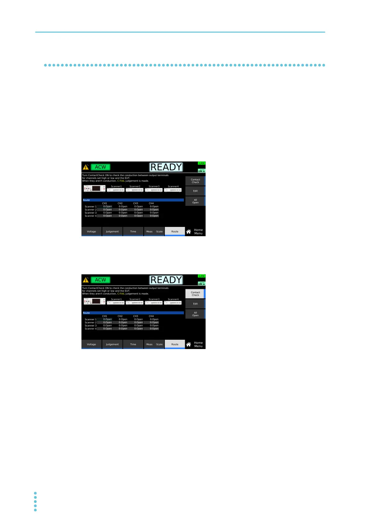
On the Home Menu screen, press Route.
2
Press Contact Check to switch between on and off.
Each time you press the key, Contact Check toggles between on and off.
This completes the setting.
If continuity cannot be confirmed
“CONTACT FAIL” will appear in the top area of the display. The U FAIL and L FAIL signals of SIG-
NAL I/O Connector (p.200) will be set to on simultaneously. On the scanner side, the LED of the cor-
responding channel lights orange. Check that the test leads are connected properly.
Example: Home menu screen of ACW
 Loading...


