COMPACT AHU WITH HEAT RECOVERY EVO-T +
OPERATION AND MAINTENANCE MANUAL
118
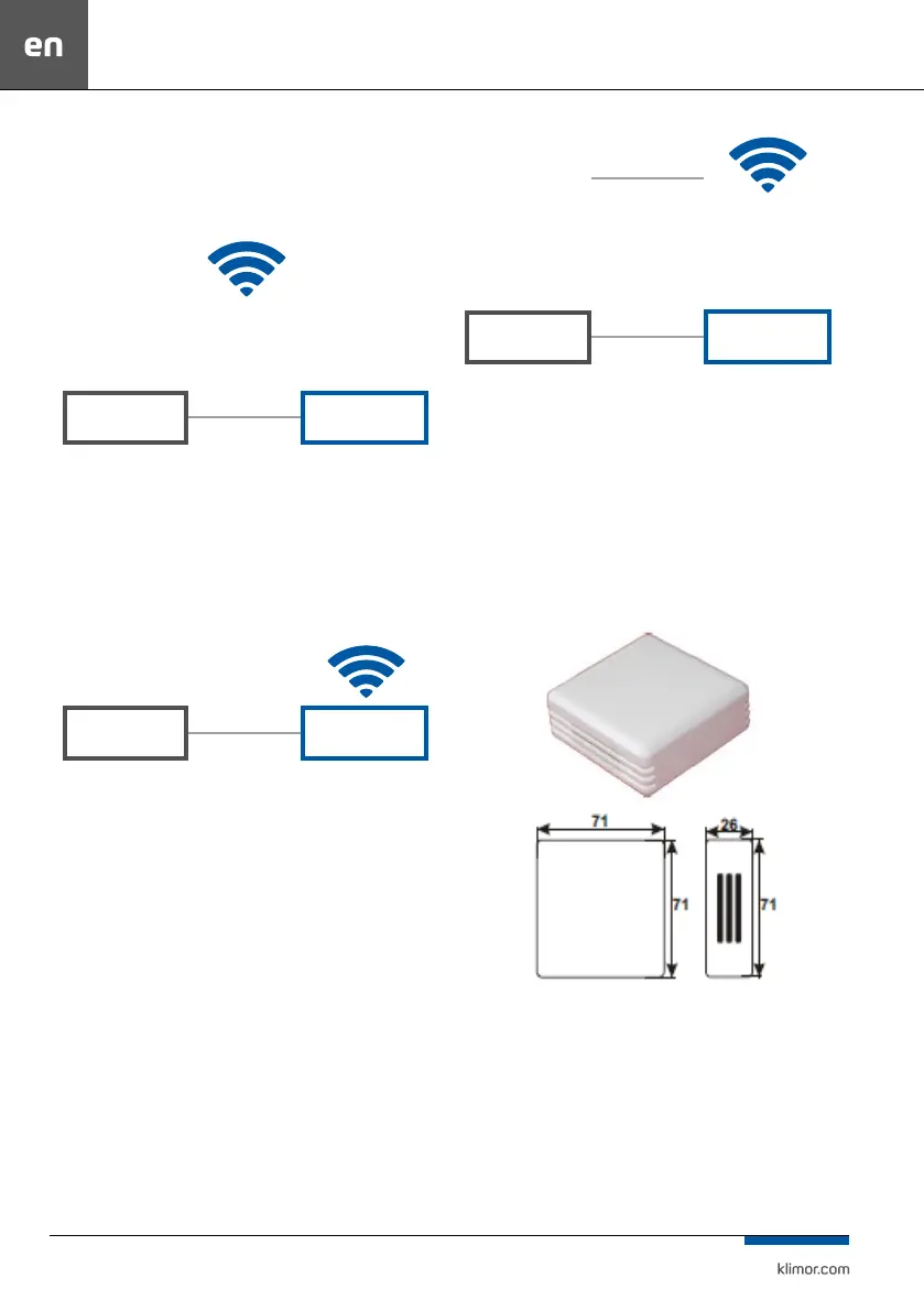
Below is a schematic example of how to establish a con-
nection in dierent ways:
1. Integration of the controller into the local network via
Wi-
LOCAL WIFI NETWORK
np. 10.10.10.1
PLC
ROUTER
192.168.0.8
DEFAULT ADDRESS
192.168.0.1
SUBNET ADDRESS
WIFI NETWORK
ADDRESS
10.10.10.31
Fig. 35 Connecting the controller to a local network via WIFI.
A router with port forwarding :80 from the ELP contro
-
ller: 192.168.0.8:80 to external address of the router:
10.10.10.31, so we see the ELP controller in the local WIFI
network. The controller is accessed via http://10.10.10.31
2. Direct communication with the controller via WIFI Router
PLC
ROUTER
192.168.0.8
DEFAULT ADDRESS
192.168.0.1
SUBNET ADDRESS
Fig. 36 Direct communication with the controller via WIFI Router.
Router with port forwarding: 80 from the controller,
that is: 192.168.0.8:80 to external address of the router:
192.168.0.1, so we see the controller in the local WIFI ne-
twork. By connecting to the router’s dedicated network we
can access the controller via http://192.168.0.8
3. Connecting the controller to a local WIFI network with
external access
Port forwarding on the main router from the WIFI router
of the controller: port:80 from IP:10.10.10.31 to external IP:
port:80 IP: 83.100.100.1
LOCAL WIFI NETWORK
np. 10.10.10.1
PLC
ROUTER
192.168.0.8
DEFAULT ADDRESS
INTERNET PROVIDER
FIXED IP ADDRESS:
Stały adres IP:
83.100.100.1
192.168.0.1
DEFAULT ADDRESS
WIFI NETWORK
ADDRESS
10.10.10.31
Fig. 37 Connecting the controller to a local WIFI network with external access.
A router with port forwarding:80 from the controller:
192.168.0.8:80 to the external address of the router:
10.10.10.31 so we can see the controller in the local WIFI
network. Connecting from any Internet connection we can
access the controller via
14.1.2 Room humidity sensor
Fig. 61
 Loading...

