87
10. CONTROL OF THE COMPACT AIR CON
DITIONING UNIT EVOT+
10.1 Assembly and connection of the control panel.
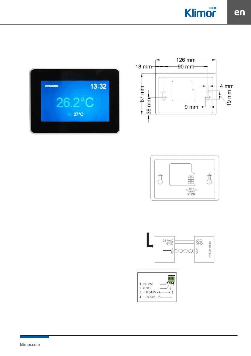
Fig. 17 Control panel view.
Power supply voltage: 24 V AC/DC +/- 10%
Power consumption max.: 2.5W
Power consumption in stand-by mode: 1W
Display resolution: 480x272 px
Colour depth: 18 bit
Touch panel: capacitive multitoutch
Communication connection: RS 485
Cooperation with ELP... series controllers
BACnet MS/TP or Modbus protocol
Built-in temperature sensor
Temperature in operation mode: +10 … 40 °C
Storage temperature: -20 … 70°C
IP Protection rating: 30
Dimensions: 126 x 87 x 16 mm
HMI has the ability to operate graphic screens (created
from JPG, PNG les), SLIDEBAR menu and TEXT menu.
On the rst screen you can see the main HMI pages. It is
agraphic menu, navigating between graphic screens takes
place after moving the screen left or right.
The SLIDEBAR sub-menu selection menu is available when
you scroll from top to bottom (being in the graphic menu).
In the SLIDEBAR menu, following submenus are available:
MAIN MENU, CALENDAR, ALARMS, GRAPH. To enter the
submenu, press the icon with the appropriate submenu
description.
Exiting the submenu is possible after moving the screen
from left to right.
The HMI programming device has its own internal settings
and in order to enter these settings you have to press any
3 points on the screen at the same time and hold for about
3 seconds.
Fig. 18 Dimensions of the panel’s back part for wall assembly.
The connection between the control panel and the unit in
line with the controller diagram 76
Fig. 19 Control panel connectors view.
With the ELP... controllers it is possible to connect the HMI to the
special HMI CON connector.
As standard every controller is equipped with
Fig. 20 Connecting the control panel to the controller.
PLC controller