81
During temperatures below 0°C and when the air supply
fan is turned o as a protecting and anti-frost function,
a short-term subatmospheric (negative) pressure will be
formed in rooms, since only air exhaust fan is operating
If the AHU installation and operation guidelines stated
above are not followed, the EVO-T+ AHUs may not operate
in line with requested parameters and humidity condensa-
tion may occur inside the unit as well as at their external
casing surfaces. If the unit is damaged and the phenomena
described above occur due to non-compliance with the re-
quirements set by the manufacturer it will result in loss of
manufacturer’s warranty
Compact Units
The unit is to be suspended with the use of handles moun-
ted on the sides of the casing. A M8 threaded bar is inserted
into the lower part of the handle (U1) and a nut with a wa-
sher is screwed on. Next, the bar is inserted into the groove
of the upper part of the handle (U2), and at the same time
they are joined together by pushing the U1 element into
the U2 element at the bottom. The use of M8 threaded bars
enables easy and quick suspension and levelling o of the
particular modules of the unit. The M8 threaded bars are
not delivered.
The minimum retained distance of the upper surface of the
unit to the partition should be 20mm (Fig. Nr 4)
Fig. 4 Installation of EVO- T+ in suspended position.
Air handling unit operation with service access from above
in a horizontal design.
The air handling unit should be located on a levelled, stable
surface. Because of the necessity of draining condensate
(installation of a siphon) it is advisable to base it on asup-
porting construction, e.g. a frame adjusted to the size of
the air handling unit (supporting construction is not sup-
plied by Klimor). Mounting using standard slings and M8
threaded rods xed to the oor is permissible and is shown
below. The minimum installation height of the EVO-T+ CPR
is 120 mm.
Fig. 5 Mounting EVO- T+ in the horizontal working position.
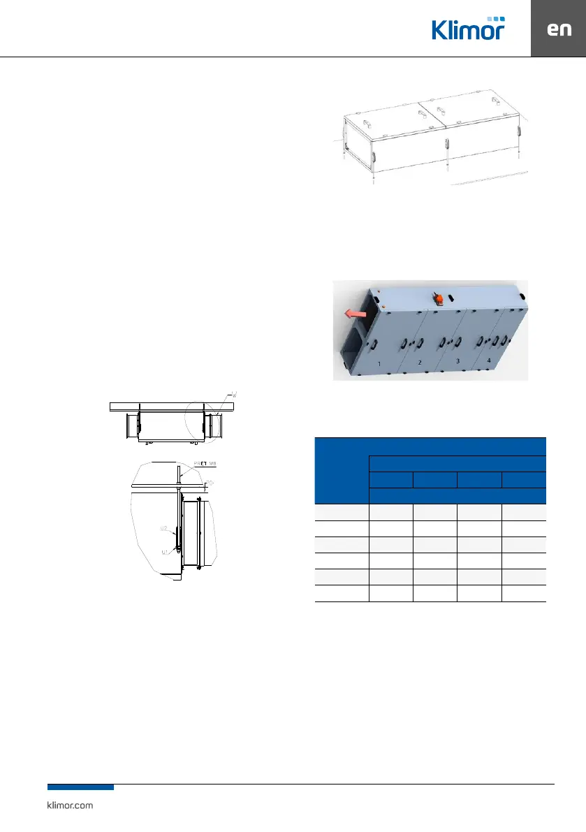
7.2 Inspection covers
When determining the place of installation of the device,
attention should be paid to easy access for maintenance
and servicing.
Fig. 6 Location of EVO-T+ inspection covers.
Table 4 Dimensions of inspection covers
EVO-T+
INSPECTION COVER
No. of the cover
1 2 3 4
mm
8000-CPR 573 x 1012 483 x1012 483 x 1012 313 x 1012
5000-CPR 808 x 712 588 x 712 -- --
3000-CPR 758 x 612 538 x 612 -- --
8000-RR 573 x 1012 573 x 1012 483 x 1012 --
5000-RR 728 x 712 568 x 712 -- --
3000-RR 678 x 612 518 x 612 -- --
7.3 Connection of air ducts.
Air ducts are connected to the air handling unit through
exible connections. They counteract vibration transfers
and compensate for minor deviation in the mutual position
of the duct and a unit. Ventilation ducts should be connect-
ed with the joint anges in the corners by means of bolts. In
order for the elastic connection to work properly, the joint
sleeve should be extended for a minimum of 110 mm. The
“earth” of the unit casing should be electrically connect-
ed with the “earth” of the ventilation network. Ventilation
ducts should have their own supports or suspensions. If in
close proximity to the air handling unit outlet there will be
elbows of the duct, it is recommended that they have the
direction matching the direction of the fan rotation.