83
7.4 Electric connection
Electric connection of the AHU must be carried out in line
with appropriate building codes and standards. Connec-
tion of electric system should be carried out only by techni-
cian with appropriate electrical qualications.
7.5 Draining out condensate
In the drip tray of CPR counterow heat exchanger, there is
a stub pipe for condensate drainage, leading to the outside
of the unit. A drain trap should be connected to the stub
pipe to ensure correct draining of the condensate and to
prevent the air suction. The drain trap is delivered with the
air handling unit as a standard.
The trap used is an all-purpose device and may work on the
suction (pressure below atmospheric) and discharge (pres-
sure above atmospheric) side of the fan. It is only required
that assembly works allow for the correct ow direction
on the condensate installation – appropriate direction is
shown on the lid.
With the EVO-T+ CPR the siphon works on the suction
side of the fan (negative pressure).
If an additional cooler is used, the siphon will operate on
the discharge side (positive pressure).
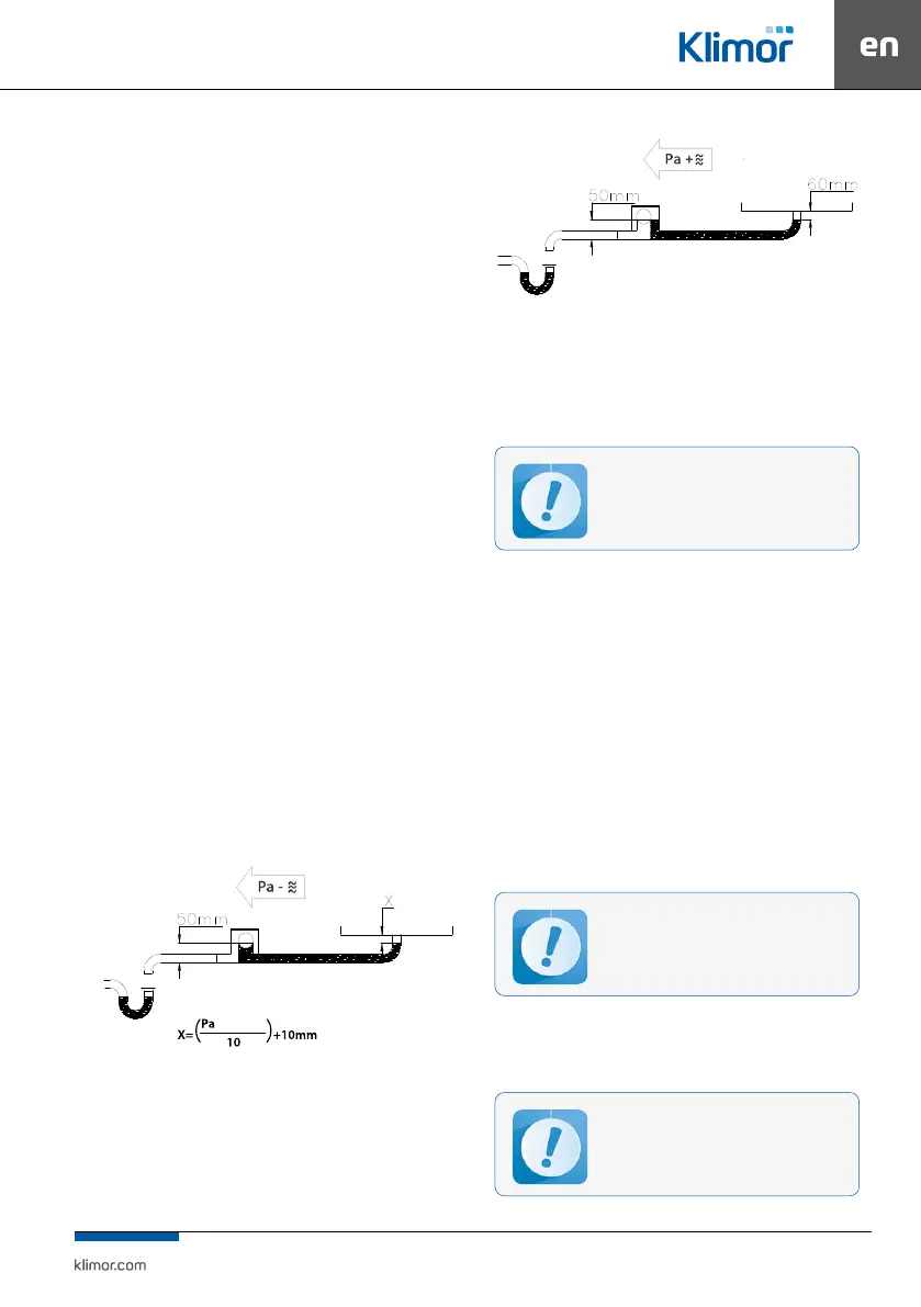
For a trap working on pressure below atmospheric an
appropriately high terminal should also be made out of
supplied PVC pipes, working out value X where the trap is
going to operate.
When using the siphon for the radiator drip tray, open the
lid on the siphon and remove the black rubber plug mount-
ed on the cylindrical ball bed and then close the lid.
The siphon trap set is also equipped with additional in-
stallation instructions. A suitable slope in the condensate
drainage system must be taken into account.
The supply and exhaust air temperature should be be-
tween -20
o
C and 40
o
C and the relative humidity should not
exceed 80%.
The installation site must provide conditions for proper
drainage of condensate.
negative pressure
Fig. 7 A trap working on negative pressure.
Fig. 8 A trap working on positive pressure.
Note:
For a trap working on positive pressure (cooler), additional-
ly the lid should be opened, the rubber plug removed, and
then the lid should be closed.
Correct condensate drainage requires
perma- nent ooding of the siphon
7.6 Connection of the remote control panel to the EVO-T+
Connection of the remote control panel should be carried
out according to the instruction described in the section 9.
“Control of the compact air conditioning unit EVO-T+”.
8. FIRST STARTUP OF THE AHU
Once the installation process and all connections (electri-
cal, ducts and controls) are complete:
• check correctness of power connections,
• check tightness of air duct connectors
• check if all other additional devices working with EVO-T+
are connected in a correct way.
If no connection faults are found you can proceed with the AHU
start-up procedure
The unit is started via the control panel.
See description in chapter CONTROL OF
THE COMPACT AIR CONDITIONING UNIT
EVO-T+ (Section 9)
• Turn on the AHU
• Adjust and preset appropriate air ow of the fans
• Adjust the temperatures.
The rst start-up of the unit requires l-
ling in the commissioning protocol.