Do you have a question about the Koden CVS-841 and is the answer not in the manual?
Warning about high voltage hazards in the transmitter section and necessary precautions.
Steps to safely disconnect power to prevent electric shock during maintenance.
Advice on using a mask when cleaning to avoid dust inhalation and potential allergies.
Caution against static discharge damaging sensitive electronic components.
Care instructions for the glass or plastic display plate to prevent mechanical damage.
Guidance on the mercury content in LCDs and proper disposal methods.
Explains the symbol indicating potential injury or equipment damage.
Explains the symbol indicating potential equipment malfunction.
Explains the symbol indicating the risk of electrical shock.
Explains the symbol indicating that an action is forbidden.
Outlines the topics covered in the manual, including installation and operation.
Describes how the manual is organized for user navigation and information retrieval.
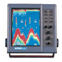
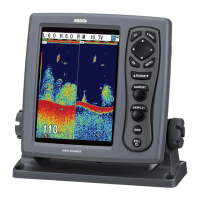
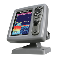
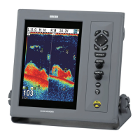
Details on display size, power output, frequency, and other key characteristics.
Information on compliance with IEC-60945 for marine electronic equipment.
Breakdown of the system components, including display, TX/RX module, and transducer.
Specifies the software type names associated with CVS-841 and CVS-851 models.
Lists standard items provided with the unit, including weights and quantities.
Catalog of spare parts that can be ordered for maintenance or repair.
Details on optional items that can enhance the system's functionality.
Information on compatible transducers, including their specifications and weights.
Technical data on display, frequencies, sounding ranges, modes, and controls.
Specifies DC input voltage range and AC operation requirements via rectifier.
Details on temperature, humidity, and vibration resistance for reliable operation.
Provides external dimensions, weight, and mounting details for display units.
Guidelines for choosing a location and performing installation safely and effectively.
Instructions for unpacking and verifying the contents of the equipment package.
Procedures for checking units for any physical or electrical damage before installation.
Recommendations for positioning the display for optimal viewing and accessibility.
Best practices for routing cables to prevent interference and ensure secure connections.
Instructions for installing the display unit using table or flush mount methods.
Diagrams and instructions for connecting the display unit, power, and transducers.
Final verification steps to ensure the system operates correctly before initial use.
Detailed pin assignments for all connectors on the unit for accurate wiring.
Guidance on recommended transducer installation locations and methods.
Description of all controls, keys, and their primary functions on the unit.
Step-by-step guide for powering on the unit and performing initial checks.
Instructions for configuring and viewing dual frequency or split-screen images.
How to use the VRM to measure depth and set zoom ranges accurately.
Setting the refresh rate for the sonar image feed.
Procedure to activate and use the IR function to reduce acoustic interference.
Using Fix Shift and Auto Shift for dynamic depth display adjustments.
How to filter out unwanted colors from the sonar display for clearer images.
Configuration of Depth Alarm and Fish Alarm parameters for audible alerts.
Marking and recording event positions, time, and navigation data instantly.
Identifies the MENU key and arrow keys used for accessing and navigating menus.
Guides users through the process of selecting menu items and adjusting settings.
Instructions on how to check and confirm the unit's initial factory configuration.
An organized list detailing all available menu functions and their parameters.
Explanations for settings related to Transmission, Image, Display, and other categories.
Options for configuring A Scope, Zoom types, Scale, and Image Direction on the display.
How to configure Auto Range and Auto Shift for automated system adjustments.
Settings for Time, Depth Units, Draft, and various sensor corrections.
Adjusting GAIN, STC, Color Palettes, Panel Lock, and Brightness.
Procedures for saving user settings and restoring factory defaults.
Instructions for activating the simulator for practice and demonstration purposes.
Procedure to assign specific depth values to selectable range numbers.
How to register preferred image settings to USER 1, USER 2, and USER 3.
Applying different zoom modes like BTM, BD, ZOOM, and B.Z. to the display.
Modifying the dynamic range of sonar video signals for improved image clarity.
Setting up the 3-division display layout and adjusting gain controls for each segment.
Key details to provide when requesting technical support.
How the unit's built-in system check operates and indicates status.
A guide to diagnosing and resolving common equipment malfunctions.
Procedure to optimize bottom detection by adjusting the video threshold setting.
Guidelines for regular maintenance to ensure optimal performance and longevity.
Instructions for cleaning the display screen using appropriate materials.
Procedure for inspecting and cleaning the transducer surface for marine growth.
Format and details of GPS position data sentences (GGA, GLL, GTD).
Explanation of the fields and syntax within NMEA input sentences.
Format and details of output data sentences (DBS, DBT, DPT, MTW, TLL).
Electrical characteristics and circuit diagrams for the data input/output serial line.
Electrical characteristics and circuit diagrams for the data input serial line.
A table summarizing user-configurable parameters and their settings.
Lists the default settings for key functions and menu options across factory configurations.
Default values for depth range presets based on factory settings and model.
| Category | Marine Equipment |
|---|---|
| Frequency | 50/200 kHz |
| Output Power | 1 kW |
| Power Output | 1 kW |
| Weight | Approx. 5 kg |
| Display | 10.4-inch color LCD |
| Operating Voltage | 12-24 V DC |