MDC-1840BB/1841BB/1860BB/1810BB/1820BB Series Chapter 4
Operation Manual Installation
0093142122-11 4-9
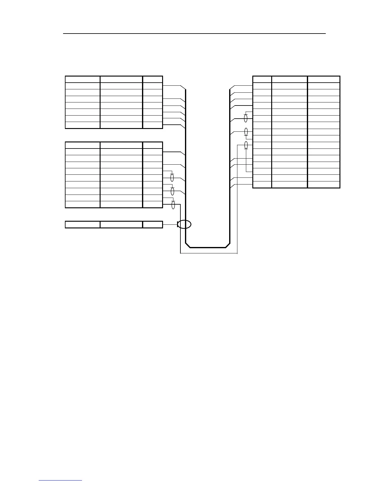
Figure 4.7 Interconnections between Antenna Unit and Display Unit
ANTENNA UNIT PROCESSOR UNIT
P1 PX
Description Color No. No. Color Description
+250V Violet 1 1 Violet +250V
NC NA 2 2 Blue +24V
GND Yellow 3 3 Orange(Larger) +12V
+40V Red(Larger) 4 4 Yellow GND
+40V Yellow (Larger) 5 5 Braid DATA-RTN
+40V-RTN Green (Larger) 6 6 Red (Coax) DATA
+40V-RTN Blue (Larger) 7 7 - -
8 Brown (Coax) BP/SHF
P2
9 Braid BP/SHF-RTN
Description Color No. 10 Gray (Coax) V/TRIG
+24V Blue 1 11 -
NC NA 2 12 Red(Larger) +40V
+12V Orange (Larger) 3 13 Yellow(Larger) +40V
DATA-RTN Braid 4 14 Braid V/TRIG-RTN
DATA Red (Coax) 5 15 Green(Larger) +40V-RTN
BP/SHF-R Braid 6 16 Blue(Larger) +40V-RTN
BP/SHF Brown (Coax) 7
V/TRIG-RTN Braid 8
V/TRIG Gray (Coax) 9
Grounding Lug
GND Braid 1