TP-6745 7/1038 Section 2 Troubleshooting
SB-697
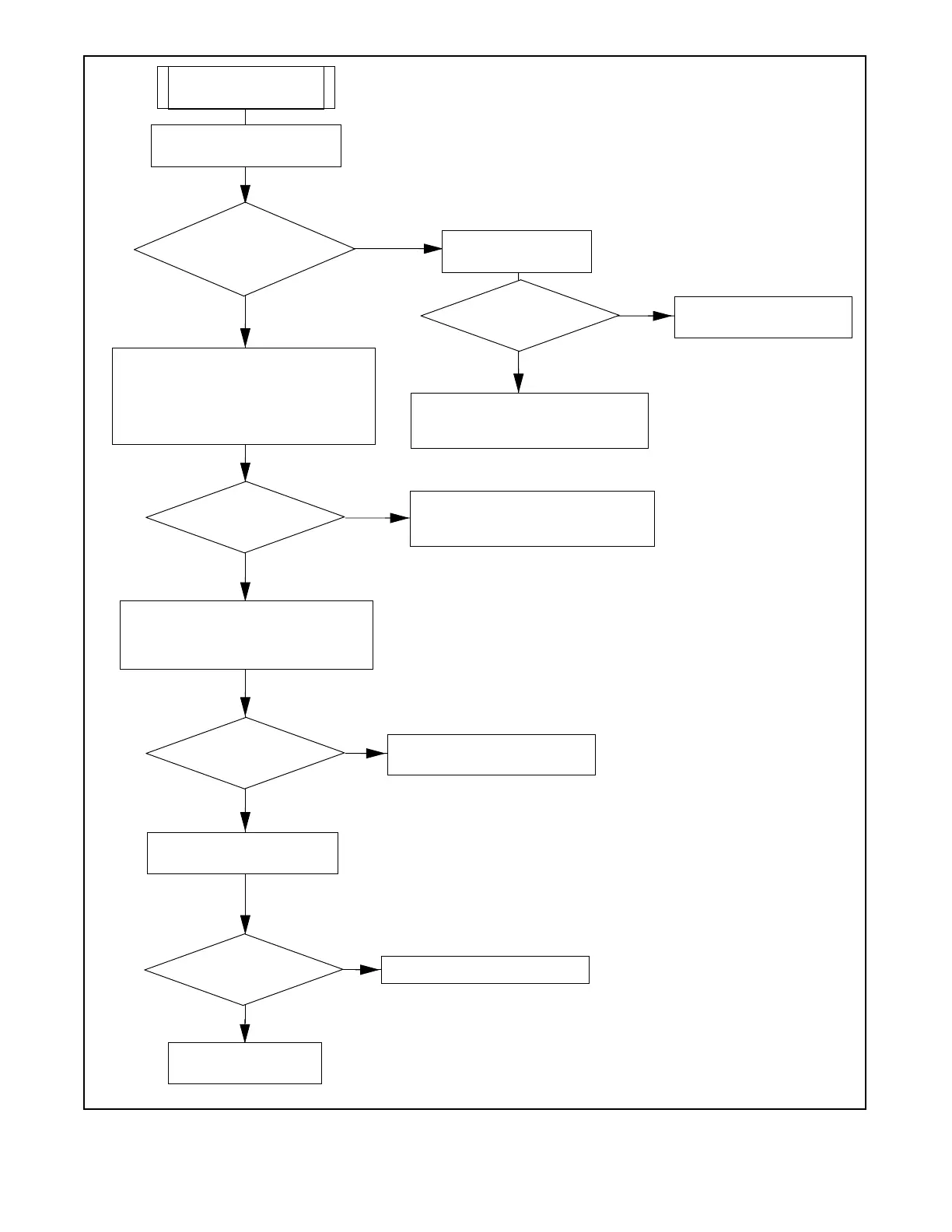
MPAC 1500 AC voltage
sensing is incorrect.
Does the controller
system voltage match the
actual system voltage?
Is the A TS rating correct
for the application?
Reprogram the controller’s system
voltage setting to the correct system
voltage.
Trace leads back to the contactor and
sensing terminals. Repair or replace
damaged leads or harness.
Verify power directly on circuit board where
P1-12, P1-11, and P1-4 (Normal) and
P1-7, P1-6, and P1-18 (Emergency) are
soldered to the board.
Measure DC voltage between
pins P16-1 and P16-2.
Replace the main logic
board (MLB).
NO
YES
YES
YES
YES
NO
NO
NO
Order a transfer switch that is
rated for the application.
NO
YES
Poor connection at P1 connector.
Identify and correct.
Replace the power supply board.
Use a digital voltmeter to verify power to the
ATS. See Figure 2-24. Check AC line
voltage at P1-12(A), P1-11(B), and P1-4(C)
for the normal source. Check AC line
voltage at P1-7(A), P1-18(B), and P1-6(C)
for the emergency source.
Line voltage found at
all points?
Line voltage found at
all points?
11 -- 13 VDC found?
Check the voltage rating
on the ATS nameplate.
Check the system voltage
programmed into the controller.
Note: To prevent damage to the controller and the device, NEVER
remove or reapply devices while the controller is energized. Follow
the safety precautions during this troubleshooting procedure.
Figure 2-19 Voltage Sensing Troubleshooting

 Loading...

