4.1.3 Parameter value PWE
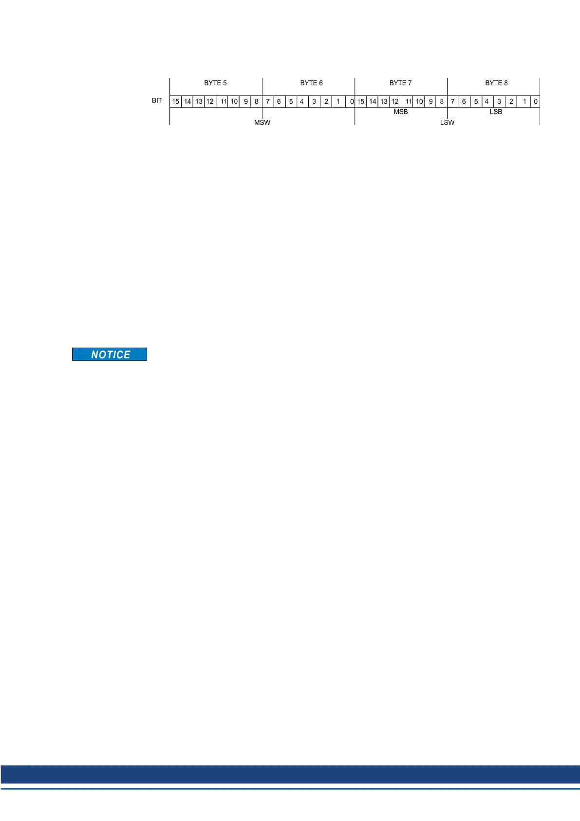
The data for the PNU-variable is contained in the PWE, and is placed flush right (PKE):
4-byte data (double-word)PWE 5-8 (PWE 8 LSB)
Commands are transferred right justified with task ID 3. If a command cannot be executed, the
response identification AK = 7 signals the error, and an error number is given out.
Error numbers (➜ # 20).
4.2 The process data channel (PZD)
Cyclical data are exchanged across the PROFIBUS through the process data section of the 20-
byte telegram. Each PROFIBUS cycle triggers an interrupt in the servo amplifier and new process
data is exchanged and processed. The interpretation of the PZD by the amplifier depends on the
operating mode that is set. The operating mode is set through a PROFIBUS parameter (PNU 930
(➜ # 27)).
In all operating modes, data word 1 of the process data (PZD1) in the direction from control sys-
tem to servo amplifier is used for instrument control, and in the direction from servo amplifier to
control system it has the function of a status indicator for the amplifier.
The interpretation of the process data PZD2 – PZD6 changes depending on the operating mode
(➜ # 41).
When the servo amplifier is switched on, the PROFIDRIVE operating mode that is always set to
–126 (safe state). Before changing the operating mode, bit 10 of the control word STW must
always be set to 0. The new operating mode only becomes active when bit 10 of the control
word is set to 1 (➜ # 27).
S300-S400-S600-S700 PROFIBUS | 4 Device profile
Kollmorgen | kdn.kollmorgen.com | December 2019 21

 Loading...


