7.1.7 Start a motion task
Motion tasks are started by a transition edge (positive or negative) at Bit 6 STW. Bit 14 STW is
used to decide whether a stored motion task or a direct motion task should be carried out.
Conditions:
Hardware enable is present.
Amplifier is in the “Operation enabled” state.
For linear axis: reference point is set.
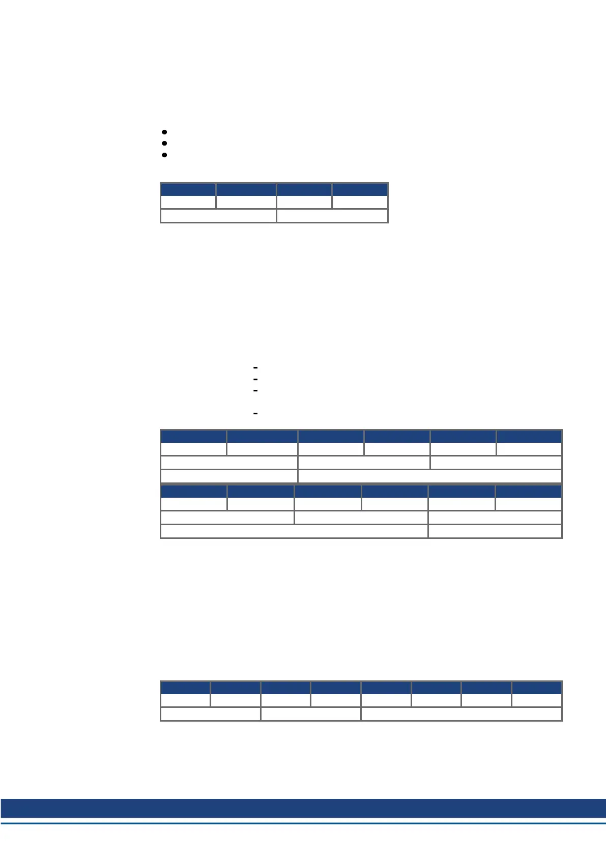
Example: start the EEPROM motion task number 10:
Byte 9 10 11 12
0000 0100 0F*11 1111 0000 0000 0000 1010
STW HSW
* F stands for a transition edge, the state of Bit 6 STW also depends on the previous state.
By setting bit 5 in the manufacturer specific status, the amplifier indicates that it has accepted the
motion task and is carrying it out.
7.1.8 Start a direct motion task
If the motion task data is to be directly sent from the controller, then a direct motion task must be
used. In this case, the target position, velocity and type of motion task are transferred using the
process data channel (PZD), together with the call of the motion task. If required, further para-
meters for this motion task (e.g. ramps) can be transferred previously by parameter tasks.
Target position 35000 µm
Velocity 20000 mm/s
Motion task type relative to actual position
with following motion task without pause
target velocity for the following task should already be reached at the tar-
get position (only makes sense if there is no change of direction)
use SI (user) units
Byte 1 2 3 4 5 6
0100 0100 0F*11 1111 0000 0000 0000 0000 0100 1110 0010 0000
PZD1 PZD2 PZD3
STW velocity setpoint
Byte 7 8 9 10 11 12
0000 0000 0000 0010 0000 1111 0101 1000 0010 0001 0001 1101
PZD4 PZD5 PZD6
position setpoint motion task type
* F stands for a transition edge, the state of Bit 6 STW also depends on the previous state.
7.1.9 Polling a warning or error message
If a warning or error message is present, then parameter 1001 or 1002 can be interrogated to find
out the number of the warning or error.
7.1.10 Writing a parameter via parameter channel
Parameter v_max is used as an example to show how control parameters are transmitted from the
master to the servo amplifier.
Parameter number: 1816 111 0001 1000
Parameter value: 350000 µm/s 0000 0000 0000 0101 0101 0111 0011 0000
Byte 1 2 3 4 5 6 7 8
0011 0111 0001 1000 0000 0100 0000 0000 0000 0000 0000 0101 0101 0111 0011 0000
PKE IND PWE
Note: After an error has occurred in parameter transmission (AK = 7), a “Zero telegram” should be
transmitted, i.e. the first 8 bytes of the transmit telegram from the PLC should be kept at 0, until the
servo amplifier has responded with a zero telegram.
S300-S400-S600-S700 PROFIBUS | 7 Appendix
Kollmorgen | kdn.kollmorgen.com | December 2019 49

 Loading...


