S300-S400-S600-S700 PROFIBUS | 7 Appendix
7 Appendix
7.1 Setup examples for all servo amplifier models
7.1.1 Zero telegram (for initialization)
At the beginning of PROFIBUS communication via the parameter channel and after com-
munication errors, a zero telegram should be sent:
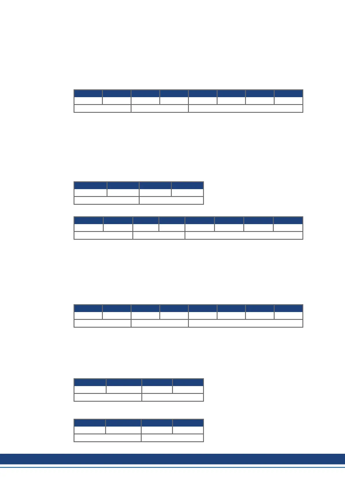
Byte 1 2 3 4 5 6 7 8
0000 0000 0000 0000 0000 0000 0000 0000 0000 0000 0000 0000 0000 0000 0000 0000
PKE IND PWE
The servo amplifier answers, by likewise setting the first 8 byte of the telegram (PKW) to zero.
7.1.2 Setting the Opmode
After switch-on or a reset (coldstart) the servo amplifier is in the PROFIBUS operating mode -126,
in which it cannot perform any motion functions. For example to carry out positioning operations
(motion tasks, jogging, homing), it must be set to the position-control mode.
The procedure to do this is as follows:
a. Set the control word Bit 10 (PZD1, Bit 10) to 0. This invalidates the process data for the
servo amplifier.
Byte 9 10 11 12
xxxx x0xx xxxx xxxx xxxx xxxx xxxx xxxx
STW HSW
b. Transmit PNU 930 through the parameter channel to set the operating mode.
Byte 1 2 3 4 5 6 7 8
0011 0011 1010 0010 xxxx xxxx xxxx xxxx 0000 0000 0000 0000 0000 0000 0000 0010
PKE IND PWE
The bits in the PKE section of the PKW have the following significance:
Bit 0 to 10 = PNU 930, Bit 12 to 15 = AK 3 (➜ # 19)
The servo amplifier sends a response telegram with AK = 2 and mirrors (identical) the values for
the PNU (parameter number) and PWE (parameter value).
c. Switch on the new operating mode by setting the control word (STW) Bit 10 to 1. This val-
idates the process data.
If, for example, point a) is not observed, the servo amplifier transmits a negative answer:
(response ID=7)
Byte 1 2 3 4 5 6 7 8
0111 0011 1010 0010 0000 0000 0000 0000 0000 0000 0000 0000 0000 0000 0001 0001
PKE IND PWE
And the number that is transferred in the PWE section represents the error number (➜ # 20). In
this case, error no. 17, “Task impossible because of operating state” will be signaled.
7.1.3 Enable the servo amplifier
The hardware enable signal (24V) must be applied, as a precondition for enabling the servo amp-
lifier via the PROFIBUS. The enable through PROFIBUS can be made by setting the bit com-
bination for the “Operation enabled” state in the control word (STW).
Byte 9 10 11 12
xxx0 x1xx 0011 1111 xxxx xxxx xxxx xxxx
STW HSW
The servo amplifier then reports back the corresponding state in its status word (ZSW), or indic-
ates a warning or error message.
Byte 9 10 11 12
xxxx xx1x 0010 0111 xxxx xxxx xxxx xxxx
ZSW HSW
46 Kollmorgen | kdn.kollmorgen.com | December 2019

 Loading...


