18. Malfunction code Field Service Ver. 1.0 Dec. 2008
256
bizhub 362/282/222
TROUBLESHOOTING
18.3 Solution
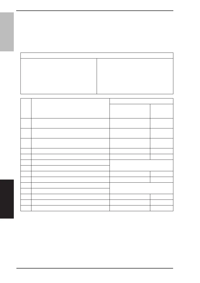
18.3.1 C0202: Tray 1 Elevator Failure
18.3.2 C0204: Tray 2 Elevator Failure
18.3.3 C0206: Tray 3 Elevator Failure
18.3.4 C0208: Tray 4 Elevator Failure
Relevant Electrical Parts
Tray1 Paper Lift Motor (M7)
Tray2 Paper Lift Motor (M8)
Tray3 Lift Motor (M124-PF)
Tray4 Lift Motor (M125-PF)
Tray1 Paper Lift Sensor (PC6)
Tray2 Paper Lift Sensor (PC12)
Tray3 Lift Sensor (PC114-PF)
Tray4 Lift Sensor (PC123-PF)
Mechanical Control Board (PWB-A)
Power Supply Unit (PU1)
Main Control Board (PWB-C2 PF)
Step Action
WIRING DIAGRAM
Control Signal
Location
(Electrical
Component)
1
Check the motor and sensor connectors for proper
connection, and correct as necessary.
--
2
Check the connector of each motor for proper drive
coupling, and correct as necessary.
--
3
Check the PU1 connector for proper connection and
correct as necessary.
--
4 PC6 I/O check PWB-A PJ15A-11 (ON) D-17
5 PC12 I/O check PWB-A PJ22A-6 (ON) D-6
6 PC114-PF I/O check
See P.27 of the PC-108/PC-206 service
manual.
7 PC123-PF I/O check
8 M7 operation check - D-23
9 M8 operation check - D-19
10 M124-PF operation check
See P.27 of the PC-108/PC-206 service
manual.
11 M125-PF operation check
12 Change PWB-A - -
13 Change PWB-C2 PF - -
14 Change PU1 - -
 Loading...