18. Malfunction code Field Service Ver. 1.0 Dec. 2008
264
bizhub 362/282/222
TROUBLESHOOTING
18.3.25 C5351: Power Supply Cooling Fan Motor Failure
18.3.26 C5352: Cooling Fan Motor Failure
18.3.27 C5353: IU Cooling Fan Motor Failure
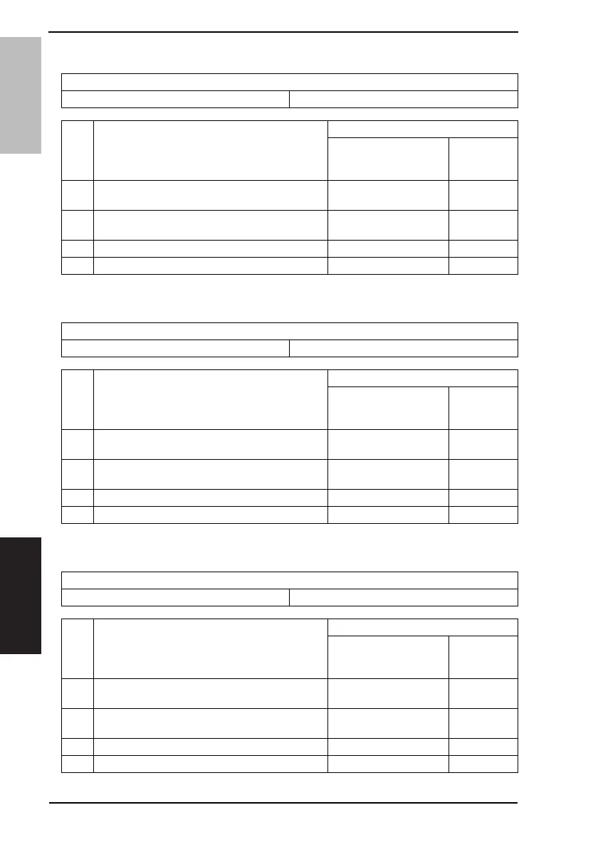
Relevant Electrical Parts
Power Supply Cooling Fan Motor (M4) Power Supply Unit (PU1)
Step Action
WIRING DIAGRAM
Control Signal
Location
(Electrical
Component)
1
Check the M4 connectors for proper connection,
and correct as necessary.
--
2
Check the fan for possible overload, and correct as
necessary.
--
3 M4 operation check PWB-A PJ33A-1 (REM) D-5
4 Change PU1 - -
Relevant Electrical Parts
Cooling Fan Motor (M5) Mechanical Control Board (PWB-A)
Step Action
WIRING DIAGRAM
Control Signal
Location
(Electrical
Component)
1
Check the M5 connectors for proper connection,
and correct as necessary.
--
2
Check the fan for possible overload, and correct as
necessary.
--
3 M5 operation check PWB-A PJ11A-6 (REM) M-8
4 Change PWB-A - -
Relevant Electrical Parts
IU Cooling Fan Motor (M6) Mechanical Control Board (PWB-A)
Step Action
WIRING DIAGRAM
Control Signal
Location
(Electrical
Component)
1
Check the M6 connectors for proper connection,
and correct as necessary.
--
2
Check the fan for possible overload, and correct as
necessary.
--
3 M6 operation check PWB-A PJ15A-1 (REM) D-16
4 Change PWB-A - -
 Loading...